
Display and Touchscreen
Overview
Embedded devices, such as smart home appliances, medical equipment, and in-vehicle infotainment system, often use displays and touchscreens. These devices are usually designed for specific tasks or functionalities, so their displays and touchscreens may have specific purposes or features.
Displays
The main role of displays in embedded devices is usually to provide an interface for users to see the device's status information, feedback, or perform operations.
- Status display: For example, a washing machine display may show the current progress of the washing program, or a microwave display may show the remaining heating time.
- Feedback information: For example, a medical monitoring device display may show a patient's vital signs such as heart rate and blood pressure.
- Operation guidance: For example, an in-vehicle infotainment system display may show maps, navigation guidance, etc.
Touchscreens
Touchscreens are typically used as input devices in embedded devices, allowing users to directly interact with the screen.
- Direct control: For example, users can select or adjust settings on a smart home appliance touchscreen, or input destinations on a car infotainment system touchscreen.
- Convenient interaction: For certain embedded devices, such as portable medical devices or industrial control devices, touchscreens provide a convenient and intuitive way of interaction.
- Multi-touch operation: Many touchscreens support multi-touch, allowing users to use more complex gestures to control the device.
In summary, the main role and function of displays and touchscreens in embedded devices is to provide a user interface that makes the device easy to use and understand.
Displays
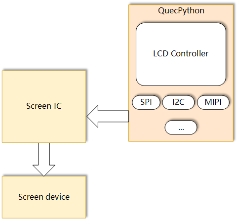
Many applications require displaying information to users, making displays an important output device. The QuecPython series modules provide rich peripheral support for screen display applications, including interfaces such as SPI and MIPI.
A display usually consists of two main parts: the display panel and the driver IC. The display panel (also known as the display substrate) determines the size, resolution, color, and other parameters of the display. The driver IC (also known as the screen controller) is matched with the display panel and packaged with the panel together. It communicates with the outside through certain interfaces and controls the display panel for display.
Types
Modern displays come in a wide variety of types, used in various devices and applications, from personal computers to commercial advertising screens, from smart phones to televisions, from gaming devices to embedded devices, etc. Here are some common types of displays:
- Liquid Crystal Display (LCD):
- Working principle: LCD displays use liquid crystal molecules to control the passage of light in order to display images. The liquid crystal itself does not emit light, so a backlight source is needed.
- Features: LCD displays are small in size, low in power consumption, and generate less heat, making them suitable for embedded systems. They can be customized in various sizes and shapes according to specific requirements.
- Applications: LCD displays are widely used in various embedded devices, such as handheld devices, instruments, home appliances, etc.
- Organic Light Emitting Diode (OLED):
- Working principle: OLED displays use the property of organic materials emitting light, by applying voltage to make the organic materials emit light, thereby displaying images. Each pixel can emit light individually.
- Features: OLED displays have vivid colors, high contrast, and fast response time, and can be manufactured as flexible and transparent displays.
- Applications: OLED displays are currently mainly used in high-end mobile devices, such as smart phones and wearable devices.
- Electronic Paper Display (E-Ink Display):
- Working principle: Electronic paper changes the display color by the microcapsules sandwiched between two transparent electrodes. Each microcapsule contains black and white particles, and applying voltage changes the position of the particles, thus changing the display color.
- Features: Electronic paper has extremely low power consumption and provides a very good reading experience, especially in lighting conditions, with high clarity.
- Applications: Electronic paper is mainly used in e-readers and gradually applied to various display tags and devices that require long-term display.
- Micro LED:
- Working principle: Micro LED displays are composed of countless tiny LED pixels, and each pixel can emit light and adjust brightness individually.
- Features: Micro LED displays have rich colors, high contrast, fast response time, low power consumption, and long lifespan.
- Applications: Currently, micro LED is mainly used in high-end large displays and televisions, but with technological advancements, it may gradually be applied to more embedded devices in the future.
These are some common types of displays in embedded systems. The display requirements in embedded systems may vary depending on specific applications and performance requirements, so choosing the appropriate type of display is crucial.
Driver Block Diagram
The relationship between the MCU/CPU, driver IC, and interface is as follows:
- Main Controller (MCU/CPU): This is the core part of the embedded system, responsible for processing data, executing code, and managing and controlling various parts of the system.
- Display Interface: This is the communication link between the MCU/CPU and the display chip. Common display interfaces include SPI, I2C, HDMI, VGA, LVDS, MIPI DSI, etc. The MCU/CPU sends data and commands to the display chip through these interfaces.
- Display Chip: The display chip receives data and commands from the MCU/CPU, and then drives the display panel to perform the corresponding display based on this information.
- Display Panel (or Display Substrate): The display panel is the part of the embedded system that actually displays the image. It contains a series of pixels that change their state according to signals from the display chip, thus displaying the image.
The MCU/CPU sends data and commands to the display chip through the display interface, and then the display chip drives the display panel to display the image according to the data and command information. This is the basic relationship between these components in an embedded system.
Compatibility Notes
Most screen controllers can support multiple display interfaces. For example, the ILI9486 supports MCU interface (i.e., 8080 interface), SPI, RGB interface, and MIPI.
QuecPython currently supports the following interfaces:
SPI
The SPI features of the QuecPython series modules are:
- The SPI clock frequency can reach up to 50 MHz.
MIPI
The MIPI features of the QuecPython series modules are:
- The MIPI clock frequency can reach up to 100 MHz.
- Supports up to 2 lanes.
The support status of MIPI and SPI on QuecPython series modules is as follows:
| SoC | MIPI | SPI |
|---|---|---|
| EC200U_XXX | √ | √ |
| EG912N_XXX | × | √ |
| EG912U_XXX | √ | √ |
| EG915N_XXX | × | √ |
| EG915U_XXX | √ | √ |
The supported screen controller models are shown in the table below:
| Controller Model | Type | Interface | Resolution | Driver | Data Sheet |
|---|---|---|---|---|---|
| ILI9225 | Color | SPI | 176*220 | ILI9225.py | ILI9225.pdf |
| ILI9341 | Color | SPI | 240*320 | ILI9341.py | ILI9341.pdf |
| ILI9806 | Color | MIPI | 480*800 | ILI9806.py | ILI9806.pdf |
| ST7735 | Color | SPI | 128*160 | ST7735.py | ST7735.pdf |
| ST7789 | Color | SPI | 240*320 | ST7789.py | ST7789.pdf |
| ST7701 | Color | MIPI | 480*854 | ST7701.py | ST7701.pdf |
| JD9365 | Color | MIPI | 800*1280 | JD9365.py | JD9365.pdf |
| SC7705 | Color | MIPI | 800*1280 | SC7705.py | SC7705.pdf |
| SSD1306 | Mono | SPI | 128*64 | SSD1306.py | SSD1306.pdf |
| UC1628 | Mono | SPI | 128*64 | UC1628.py | UC1628.pdf |
Note: When you use the LCD method, as long as the parameters are transmitted correctly, it is theoretically possible to support any SPI or MIPI screen.
Driver Structure
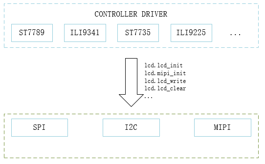
In order to have more control over the screen, QuecPython allows Python scripts to drive the screen through the parameters passed to lcd.lcd_init.
In terms of design, the only difference in driving different screens is the parameters in the scripts lcd.lcd_init or lcd.mipi_init.
Screen Classification
Classifying screens will help us understand the drivers better. Here, screens will be classified based on the colors they can display rather than the panel materials such as OLED or LCD. In general, the colors displayed on the screen determine the BPP (Bits Per Pixel), and different BPP values result in slightly different processing methods in the program. The following lists several ways in which GRAM is mapped to pixels:

Structure of BPP = 16 GRAM
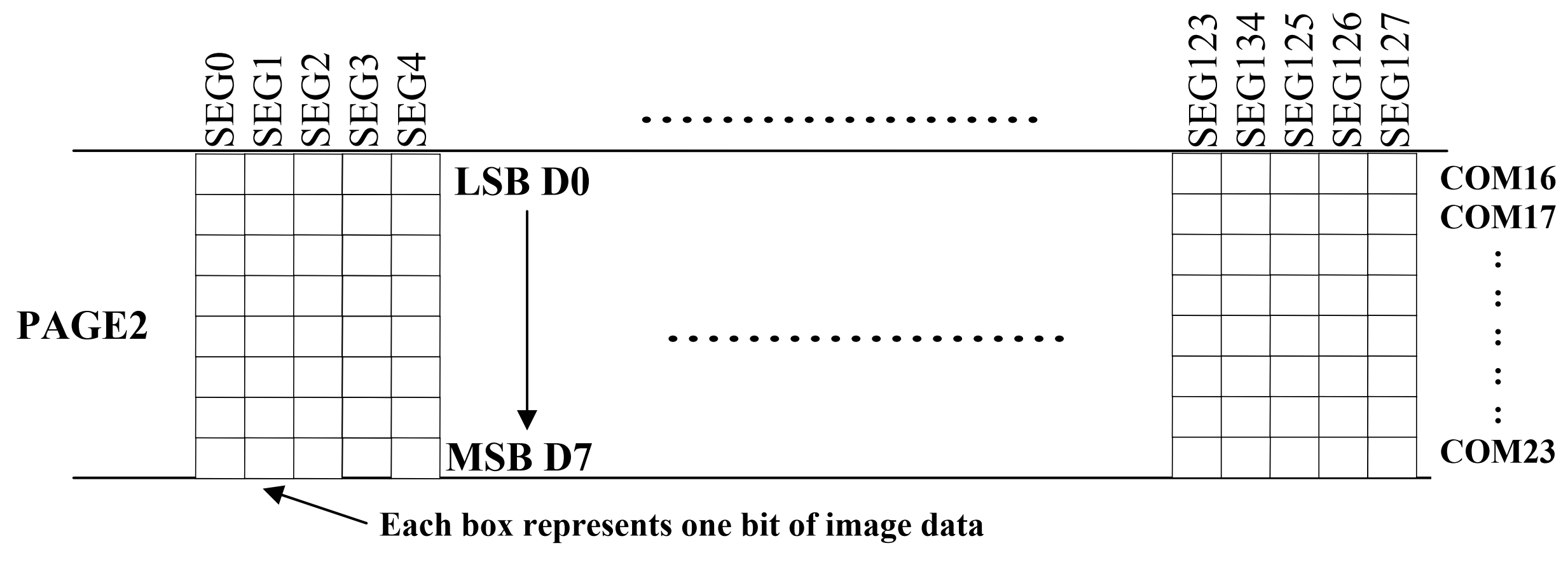
Structure of BPP = 1 GRAM
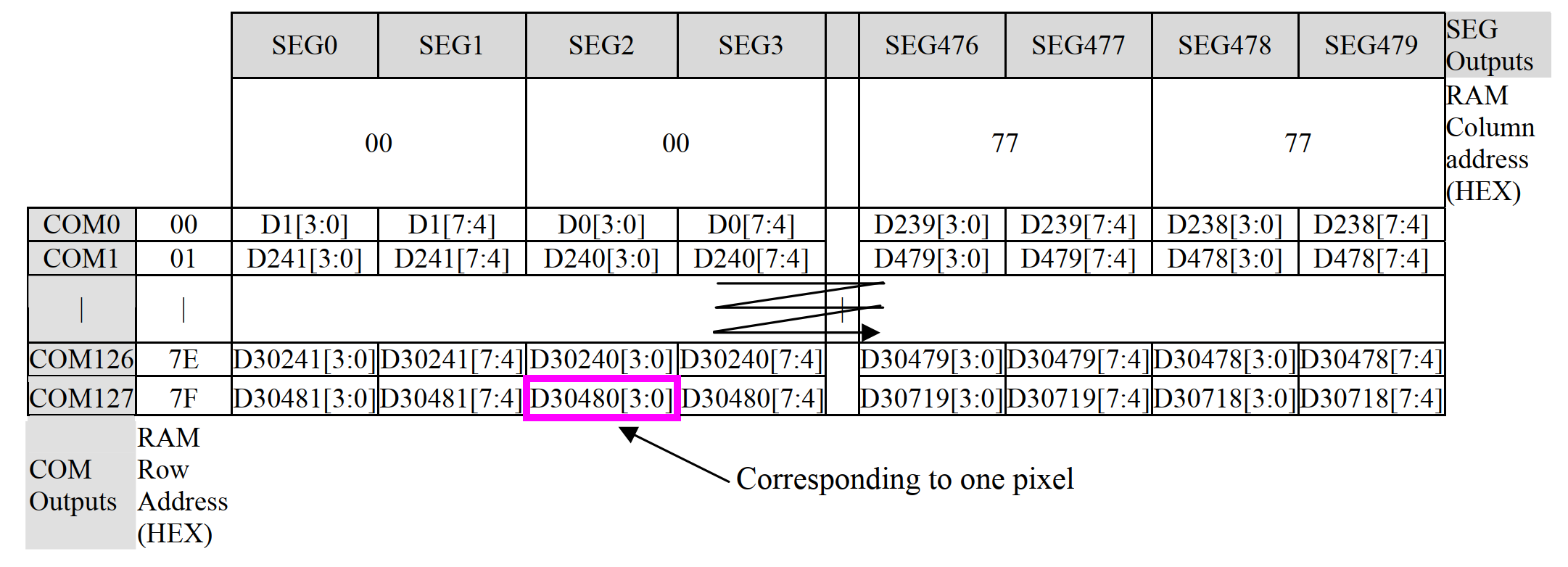
Structure of BPP = 4 GRAM
From the above figures, it can be seen that the mapping methods can be roughly divided into two categories:
- BBP >= 8, usually supports color screens with RGB888, RGB666, RGB565, and other encodings.
- BPP < 8, usually monochrome screens, which can be black and white or grayscale.
When BPP < 8, one byte is mapped to multiple pixels, so it is not possible to directly control individual pixels. However, in order to better control monochrome screens, QuecPython still passes RGB565 data to the lcd_write interface, and the system automatically converts it. This allows Python scripts to access individual pixels. When BPP >= 8, individual pixels can be easily accessed.
Note: For color screens, the driver only supports RGB565 color encoding.
Screen Controller Driver
This section will implement display and other functions based on different screen controllers.
Display Orientation
The screen display orientation is completely implemented by the screen hardware, and this function may vary on different screen controllers. There are a total of 8 possible display orientations, where the display can be rotated 0°, 90°, 180°, or 270°, and can be viewed from the top or bottom. The default orientation is 0° and top view. These 8 (4 × 2) different display orientations can also be represented as combinations of 3 binary switches: X-mirroring, Y-mirroring, and X/Y swapping.
The following table lists all 8 combinations of display orientations. If the display orientation is not correct, please refer to the configuration switches in the table to make it work correctly.
 |
L2R_U2D |  |
Y-mirroring [L2R_D2U] |
|---|---|---|---|
 |
X_mirroring [R2L_U2D] |
 |
X-mirroring Y-mirroring [R2L_D2U] |
 |
X/Y swapping [U2D_L2R] |
 |
X/Y swapping Y-mirroring [D2U_L2R] |
 |
X/Y swapping X-mirroring [U2D_R2L] |
 |
X/Y swapping X-mirroring Y-mirroring [D2U_R2L] |
For different screen controllers, the implementation of screen display orientation is not exactly the same. Generally, it can be divided into the following cases:
- For color screens, 8 orientations are supported.
- For monochrome screens, such as SSD1306, only the first 4 orientations are supported, and the XY axis cannot be swapped.
Note:
The display orientation is also related to the screen panel used. You may encounter two abnormal situations:
- The display orientation is set to L2R_U2D, but the screen does not match the corresponding display orientation in the table. This may be because the wiring on the screen panel has mirrored the X/Y direction. In this case, adjust the rotation according to the actual situation to achieve the desired display orientation.
- After rotating the screen, the displayed content disappears. This may be because the resolution of the screen panel is smaller than the resolution of the screen controller, causing the displayed area to not completely fall on the screen panel after rotation. In this case, you should consider setting the correct display area offset.
Common Screen Parameter Analysis
The screen driver IC contains multiple registers that control various functions and settings. Here are some register parameters you may need to pay attention to:
Mode registers: These registers typically control the display mode (such as resolution, color depth, etc.) and power management mode. For example, some screen driver ICs may have dedicated registers for switching between sleep mode and normal mode.
Control registers: Control registers are used to configure various features of the screen driver IC, such as screen rotation, flipping, inversion, etc.
Timing registers: These registers are used to control the timing of pixel clock, horizontal and vertical sync signals.
Gamma registers: Gamma registers are used to set the gamma correction of the screen. This is important for image quality and color accuracy.
RAM registers: RAM registers are used to store frame buffer data. The driver IC reads data from these registers and sends the data to the screen.
Status registers: Status registers allow you to read the current status of the IC, such as whether it is working normally or if any errors have occurred.
Brightness/contrast registers: Some driver ICs may have these registers to adjust the brightness or contrast of the screen.
Offset registers: These registers are usually used to control the position of the image on the screen.
Note: Each screen driver IC has its own register mapping and functionality. So when starting to use a new driver IC, you should read its datasheet to understand the details of its registers.
API Documentation
For detailed API, please refer to LCD - LCD Driver.
Note: This section provides information about the QuecPython LCD driver's related APIs. Before driving the screen, please read it carefully.
Screen Debugging
SPI LCD
SPI LCD displays are LCD screens that communicate through SPI. The advantage of this type of display is its simple interface and fewer wires, making the hardware wiring more concise. They are very suitable for microcontrollers and other resource-limited systems.
In SPI LCD, data and commands are sent to the display via the MOSI line, while the SCLK line is used to synchronize data transmission. The CS line is used to select a specific device for communication when communicating with multiple devices.
Normally, the controller (such as a microcontroller) sends appropriate commands and data through SPI based on the specifications of the display (such as resolution and color depth) and the content to be displayed. This may include setting display parameters, writing pixel data, etc.
This section will introduce the debugging of SPI LCD based on the QuecPython EVB driving the [st7789 (240*320)](TODO 链接) screen.
Preparations
Before implementing the LCD driver, we need some preparations. This part introduces the preparations needed for driving a screen. Ii is necessary to know with the LCD interface of QuecPython LCD driver, the parameters required by the interface. For the screen, you should know the ID, the type of the driver IC, and relevant commands.
Note: The initialization parameters provided by the manufacture are very important because they are replaced with the format required by lcd.lcd_init when the SPI LCD is initialized.
Understanding the QuecPython LCD interface is essential for better utilizing it to light up the screen.
Note: Currently, QuecPython SPI drivers are divided into two types: LCM (Liquid Crystal Module) and general SPI (Serial Peripheral Interface). The initialization interfaces of the two types are different. For specific details, please refer to the QuecPython LCD interface .
Understanding the parameters in LCD.lcd_init is crucial for driving LCD with QuecPython. Please read the following content carefully.
The parameter format is as follows:
type + len + value
| Parameter | Meaning | Description |
|---|---|---|
| type | Type | Indicates the type of value: 0: Command 1: Data 2: Delay |
| len | Number of data | If type is 0 (command), len indicates how many data will follow. If type is 1 (data), len indicates the length of the data. Note: The data can be 1 byte or 2 bytes. If type is 2 (delay), len has no actual meaning and is set to 0. |
| value | Data | If type is 0 (command), value indicates the command value. If type is 1 (data), value indicates the data value. If typeis 2 (delay), value indicates the duration of the delay in milliseconds. |
Note: Since the parameters of lcd_init passed are in bytearray, they need to be converted. Subsequent parameters for initialization, area write screen, screen on/off, etc., are all based on this format.
Here is an example:
init = (
0,1,0xXX,   #Command. The following is one piece of data and the command value is 0xXX
1,2,0xXX,0xXX,  #Data. The data length is 2 and the data value is 0x0100
2,0,120,    #Delay 120 ms
0,2,0xXX,   #Command. The following is two pieces of data and the command value is 0xXX
1,1,0xXX,   #Data. The first data value of the command is 0xXX
1,2,0xXX,0xFF #Data. The length of the second data value is 2 and the value is 0xXXFF
…
)
Initialization Parameters
This section is crucial and prone to errors, so please pay close attention.
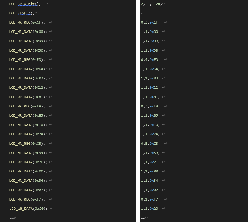
The parameters in this section are primarily derived from the source code provided by the screen manufacturer, which is mostly in C language. Below converts the C code into the parameters required for lcd_init. Here is an example of the conversion:
Tip: In VSCode, use a regular expression to replace the original text to quickly generate the parameters required in lcd_init.
Parameters of Writing on Specific Screen Area
Different LCD screens have different ways of configuring the regions. After configuring these parameters, it is unnecessary to concern about the calling details of the low-level.
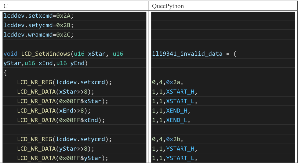
There are generally two ways to configure the screen regions (taking ili9225 and st7789v as examples):
Write in Two Steps: This method involves writing the high eight bits and low eight bits separately. The specific parameters depend on the screen driver (e.g., st7789v).
Write 2 bytes at a time (e.g., ili9225).
There are several important parameters related to the display region that need to be understood.
XSTART_H = 0xf0     # Represents the high eight bits of the X starting coordinate (When written with this value, the low-level recognizes it as the high bit of the X coordinate).
XSTART_L = 0xf1     # Represents the low eight bits of the X starting coordinate (When written with this value, the low-level recognizes it as the low bit of the X coordinate).
YSTART_H = 0xf2     # Represents the high eight bits of the Y starting coordinate.
YSTART_L = 0xf3     # Represents the low eight bits of the Y starting coordinate.
XEND_H = 0xE0       # Represents the high eight bits of the X ending coordinate.
XEND_L = 0xE1       # Represents the low eight bits of the X ending coordinate.
YEND_H = 0xE2       # Represents the high eight bits of the Y ending coordinate.
YEND_L = 0xE3       # Represents the low eight bits of the Y ending coordinate.

XSTART = 0xD0       # Represents the starting X coordinate.
XEND = 0xD1         # Represents the ending X coordinate.
YSTART = 0xD2       # Represents the starting Y coordinate.
YEND = 0xD3         # Represents the ending Y coordinate.
Note: This parameter is a locator to replace the local coordinates when you perform partial screen refresh through lcd.lcd_write of the low level.
#Example
#ILI9225 – Write 2 bytes at a time
ili9225_invalid = (
0,1,0x36,
1,2,XEND,
0,1,0x37,
1,2,XSTART,
0,1,0x38,
1,2,YEND,
0,1,0x39,
1,2,YSTART,
0,1,0x20,
1,2,XSTART,
0,1,0x21,
1,2,YSTART,
0,1,0x22,
)

#st7789v - Write in two steps. Write 1 byte at a time:
st7789_invalid = (
0,4,0x2a,
1,1,XSTART_H,
1,1,XSTART_L,
1,1,XEND_H,
1,1,XEND_L,
0,4,0x2b,
1,1,YSTART_H,
1,1,YSTART_L,
1,1,YEND_H,
1,1,YEND_L,
0,0,0x2c,
)
The example of C language to Python provided by the manufacture is as follows:
!
Screen On/Off Parameters
Because the screen-on command varies from each LCD, users need to provide this parameter. This parameter depends on the specific screen being driven.
Take ST7789V as an example:
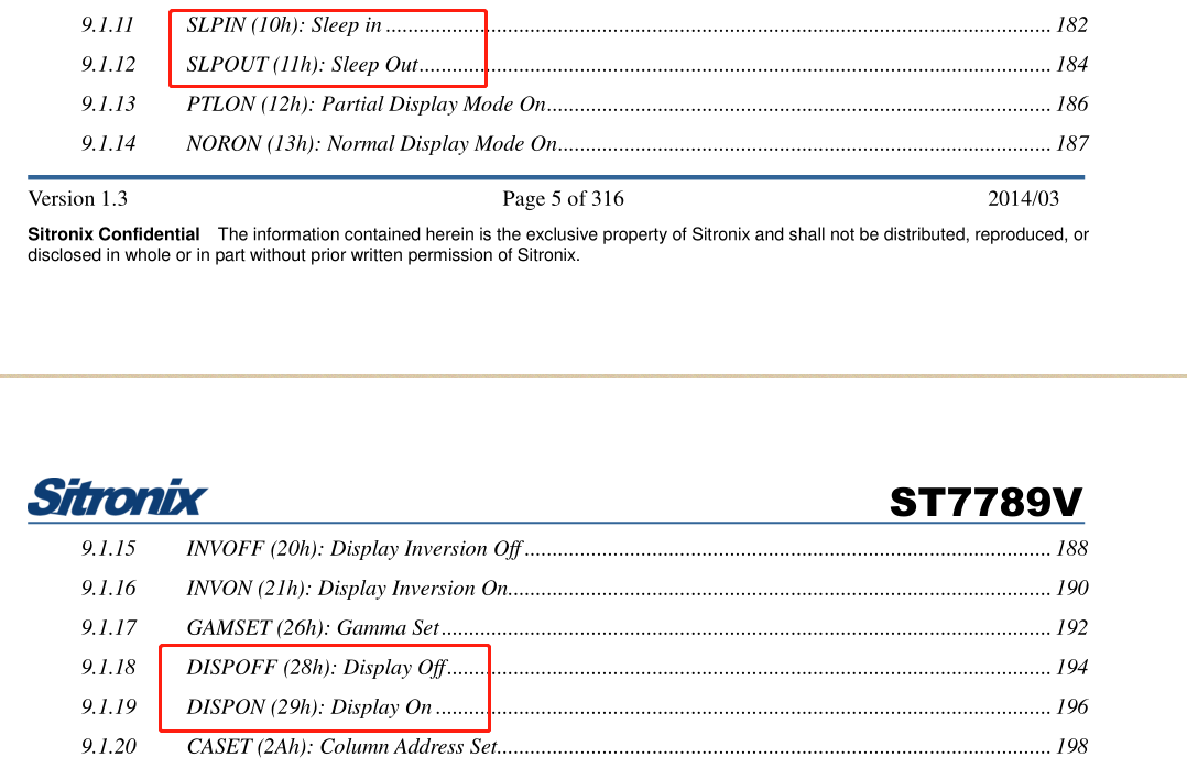
Based on the information in the diagram, the screen-on and screen-off parameters for this LCD are confirmed to be 29h and 28h respectively. The commands for exiting sleep mode and entering sleep mode are 11h and 10h respectively. This determines the parameters for turning the screen on and off (or can be determined from examples provided by the screen manufacturer).
Thus the parameters for turning the screen on and off are as follows.
lcd_displayON_data = (
0,0,0x11,       #The write command is 0x11 without any data followed
2,0,120,         #Delay 120 ms
0,0,0x29,       #The write command is 0x29 without any data followed
)
lcd_displayON_data = bytearray(lcd_displayON_data)

lcd_displayOFF_data = (
0,0,0x28,       #The write command is 0x28 without any data followed
2,0,120,        #Delay 120 ms
0,0,0x10,       #The write command is 0x10 without any data followed
)
lcd_displayOFF_data = bytearray(lcd_displayOFF_data)
Script Writing
Creating Objects
from machine import LCD
mipi_lcd = LCD()
Introduction to SPI LCD Initialization Interfaces
Please refer to LCM Interface and SPI LCD Interface for more information.
Writing Initialization Parameters
Pass the parameters from the earlier preparation to lcd.lcd_init following the order provided in the interface documentation.
Take ST7789V as an example:
XSTART_H = 0xf0
XSTART_L = 0xf1
YSTART_H = 0xf2
YSTART_L = 0xf3
XEND_H = 0xE0
XEND_L = 0xE1
YEND_H = 0xE2
YEND_L = 0xE3
XSTART = 0xD0
XEND = 0xD1
YSTART = 0xD2
YEND = 0xD3

init_st7789_240X320=(
0, 0, 0x11,
2, 0, 120,
0, 0, 0x00,
0, 1, 0x36,
1, 1, 0x00,
0, 1, 0x3A,
1, 1, 0x05,
0, 1, 0x35,
1, 1, 0x00,
0, 1, 0xC7,
1, 1, 0x00,
0, 1, 0xCC,
1, 1, 0x09,
0, 5, 0xB2,
1, 1, 0x0C,
1, 1, 0x0C,
1, 1, 0x00,
1, 1, 0x33,
1, 1, 0x33,
0, 1, 0xB7,
1, 1, 0x35,
0, 1, 0xBB,
1, 1, 0x36,
0, 1, 0xC0,
1, 1, 0x2C,
0, 1, 0xC2,
1, 1, 0x01,
0, 1, 0xC3,
1, 1, 0x0D,
0, 1, 0xC4,
1, 1, 0x20,
0, 1, 0xC6,
1, 1, 0x0F,
0, 2, 0xD0,
1, 1, 0xA4,
1, 1, 0xA1,
0, 14, 0xE0,
1, 1, 0xD0,
1, 1, 0x17,
1, 1, 0x19,
1, 1, 0x04,
1, 1, 0x03,
1, 1, 0x04,
1, 1, 0x32,
1, 1, 0x41,
1, 1, 0x43,
1, 1, 0x09,
1, 1, 0x14,
1, 1, 0x12,
1, 1, 0x33,
1, 1, 0x2C,
0, 14, 0xE1,
1, 1, 0xD0,
1, 1, 0x18,
1, 1, 0x17,
1, 1, 0x04,
1, 1, 0x03,
1, 1, 0x04,
1, 1, 0x31,
1, 1, 0x46,
1, 1, 0x43,
1, 1, 0x09,
1, 1, 0x14,
1, 1, 0x13,
1, 1, 0x31,
1, 1, 0x2D,
0, 0, 0x29,
0, 1, 0x36,
1, 1, 0x00,
0, 0, 0x2c,
)
init_st7789_240X320_p = bytearray(init_st7789_240X320)
invalid_st7789_240X320 = (
0,4,0x2a,
1,1,XSTART_H,
1,1,XSTART_L,
1,1,XEND_H,
1,1,XEND_L,
0,4,0x2b,
1,1,YSTART_H,
1,1,YSTART_L,
1,1,YEND_H,
1,1,YEND_L,
0,0,0x2c,
)
invalid_st7789_240X320_p = bytearray(invalid_st7789_240X320)

displayOFF_st7789_240X320 = (
0,0,0x28,
2,0,120,
0,0,0x10,
)
displayOFF_st7789_240X320_p = bytearray(displayOFF_st7789_240X320)

displayON_st7789_240X320 = (
0,0,0x11,
2,0,20,
0,0,0x29,
)
displayON_st7789_240X320_p = bytearray(displayON_st7789_240X320)
from machine import LCD
spilcd = LCD()
spilcd.lcd_init(init_st7789_240X320_p, 240,320,52000,1,4,0,invalid_st7789_240X320_p,displayON_st7789_240X320_p,displayOFF_st7789_240X320_p,None)
The effect is as follows:

Area Write Screen
This interface is very important as it is used to draw UI on the screen.
Note:
The screen data in QuecPython solution is in big-endian mode.
Example (ST7789V):
buf = bytearray(10240) # Here the values of buf are all 0, and the color is black
spilcd.lcd_write(buf,110,150,130,170)
The screen is displayed as follows:

Clear Screen
Example (ST7789V):
spilcd.lcd_clear(0xf800) #0xf800 is represented in red in RGB565
The screen is displayed as follows:

Image Display
Note: This interface is not supported by all modules. Please consult Quectel Technical Support for specific supporting status.
Example (ST7789V):
spilcd.lcd_show_jpg("usr/background1.jpeg", 0, 0)
The screen is displayed as follows:

MIPI LCD
The MIPI protocol is actually a series of interface protocols, including LCD, camera, etc. The MIPI interface used in LCDs is called DSI, which stands for Display Serial Interface. As the name suggests, this interface is a serial interface used for display modules. It is based on the MIPI protocol and is compatible with DPI (Display Pixel Interface), DBI (Display Bus Interface), and DCS (Display Command Set).
This chapter will drive the ST7701S (480*854) screen on the QuecPython U-235 EVB and introduce the debugging of MIPI LCD.
Since the relevant API for LCD under QuecPython has been developed, users can directly write the MIPI screen driver according to the API format.
Note: Currently QuecPython series modules that support MIPI only support the RGB565 format .
Note: In actual use, LCD is often used in conjunction with UI (LVGL).
Preparations
For the MIPI screen to be used, consult and read its datasheet and the technical manual of the driver IC to understand the characteristics of the screen and determine the initialization parameters of the screen (resolution, number of lanes, etc.). The initialization parameters of the screen can be obtained from the screen manufacturer.
Note: The initialization parameters provided by the manufacturer are very important. When initializing the MIPI LCD later, these parameters will be replaced with the parameters in the format that is required by lcd.mipi_init.
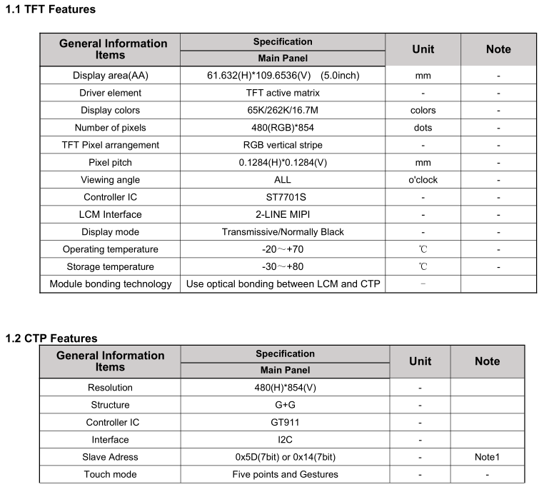
From the screen datasheet provided by the manufacturer, the screen resolution is 480*854, the driver IC is ST7701S, the interface is 2-LINE MIPI, the touch IC is GT911 and the touch interface is I2C.
Script Writing
Creating LCD Object
from machine import LCD
mipi_lcd = LCD()
Introduction to MIPI Initialization Interface
lcd.mipi_init(initbuf, **kwargs)
| Parameter | Type | Description |
|---|---|---|
| initbuf | bytearray | Required. Write command for passing MIPI. |
| width | int | Width of LCD screen. Default value: 480. Example: width = 400. |
| hight | int | Height of LCD screen. Default value: 854. Example: height = 800. |
| bpp | int | Bits per pixel. Default value: 16. |
| DataLane | int | Data channel. Default value: 2. |
| MipiMode | int | Mode: 0: DSI_VIDEO_MODE 1: DSI_CMD_MODE Default value: 0 |
| PixelFormat | int | Pixel format: 0: RGB_PIX_FMT_RGB565 16: RGB_PIX_FMT_RGB888 32: RGB_PIX_FMT_XRGB888 48: RGB_PIX_FMT_RGBX888 Default value: 0 |
| DsiFormat | int | DSI format: 0: DSI_FMT_RGB565 1: DSI_FMT_RGB666 2: DSI_FMT_RGB666L 3: DSI_FMT_RGB888 Default value: 0 |
| TransMode | int | Transform mode: 0: DSI_CMD 1: DSI_PULSE 2: DSI_EVENT 3: DSI_BURST Default value: 3 |
| RgbOrder | int | RGB order: 0: RGB 8: BGR Default value: 8 |
| BllpEnable | bool | Enable blank low power. Default value: true. |
| HSync | int | Horizontal synchronization. Default value: 10. |
| HBP | int | Horizontal back porch. Default value: 10. |
| HFP | int | Horizontal front porch. Default value: 10. |
| VSync | int | Vertical Synchronization. Default value: 4. |
| VBP | int | Vertical back porch. Default value: 10. |
| VFP | int | Vertical front porch. Default value: 14. |
| FrameRate | int | Frame rate. Default value: 60. |
| TESel | bool | TE selection. Default value: false. |
| RstPolarity | int | Reset polarity. Default value: 1. |
Writing Initialization Parameters
This part is prone to errors and is very important. Please pay special attention to it.
The parameter format is as follows:
cmd + delay_ms + data_len + data_list
| Parameter | Meaning | Description |
|---|---|---|
| cmd | Command | Command value during initialization |
| delay_ms | Delay | Delay before sending command. Unit: ms. |
| data_len | Data Length | Number of data items associated with the command |
| data_list | Data | Actual data associated with the command, the number is specified by data_len |
Note: Since the parameters of lcd_init passed are in bytearray, they need to be converted.
Example (st7701s):
These parameters are mainly derived from the source code provided by the screen manufacturer.
init_480X854 = (
0x11,0,0,                              # The command is 0x11 with 0 ms delay and no parameter is followed after the command
0xFF,120,5,0x77,0x01,0x00,0x00,0x10,   # The command is 0xFF with 120 ms delay and the command has 5 pieces of data, which are 0x77,0x01,0x00,0x00,0x10
0xC0,0,2,0xE9,0x03,                    # The command is 0xC0 with 0 ms delay and the command has 2 pieces of data, which are 0xE9,0x03
0xC1,0,2,0x11,0x02,                    # ... and so on
0xC2,0,2,0x31,0x08,
0xCC,0,1,0x10,
0xB0,0,16,0x00,0x0D,0x14,0x0D,0x10,0x05,0x02,0x08,0x08,0x1E,0x05,0x13,0x11,0xA3,0x29,0x18,
0xB1,0,16,0x00,0x0C,0x14,0x0C,0x10,0x05,0x03,0x08,0x07,0x20,0x05,0x13,0x11,0xA4,0x29,0x18,
0xFF,0,5,0x77,0x01,0x00,0x00,0x11,
0xB0,0,1,0x6C,
0xB1,0,1,0x43,
0xB2,0,1,0x07,
0xB3,0,1,0x80,
0xB5,0,1,0x47,
0xB7,0,1,0x85,
0xB8,0,1,0x20,
0xB9,0,1,0x10,
0xC1,0,1,0x78,
0xC2,0,1,0x78,
0xD0,0,1,0x88,
0xE0,100,3,0x00,0x00,0x02,
0xE1,0,11,0x08,0x00,0x0A,0x00,0x07,0x00,0x09,0x00,0x00,0x33,0x33,
0xE2,0,13,0x00,0x00,0x00,0x00,0x00,0x00,0x00,0x00,0x00,0x00,0x00,0x00,
0xE3,0,4,0x00,0x00,0x33,0x33,
0xE4,0,2,0x44,0x44,
0xE5,0,16,0x0E,0x60,0xA0,0xA0,0x10,0x60,0xA0,0xA0,0x0A,0x60,0xA0,0xA0,0x0C,0x60,0xA0,0xA0,
0xE6,0,4,0x00,0x00,0x33,0x33,
0xE7,0,2,0x44,0x44,
0xE8,0,16,0x0D,0x60,0xA0,0xA0,0x0F,0x60,0xA0,0xA0,0x09,0x60,0xA0,0xA0,0x0B,0x60,0xA0,0xA0,
0xEB,0,7,0x02,0x01,0xE4,0xE4,0x44,0x00,0x40,
0xEC,0,2,0x02,0x01,
0xED,0,16,0xAB,0x89,0x76,0x54,0x01,0xFF,0xFF,0xFF,0xFF,0xFF,0xFF,0x10,0x45,0x67,0x98,0xBA,
0xFF,0,5,0x77,0x01,0x00,0x00,0x00,
0x3A,0,1,0x77,
0x36,0,1,0x00,
0x35,0,1,0x00,
0x29,0,0)
from machine import LCD
mipilcd = LCD()
mipilcd.mipi_init(initbuf=bytearray(init_480X854), TransMode=1)
The screen is displayed as follows:
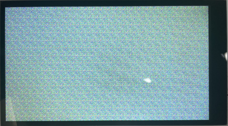
Note: The screen flickering is a normal phenomenon. The data in the display buffer is random data, which causes the screen to display random pixels, resulting in flickering. Clearing the screen will solve this problem.
Area Screen Writing
This interface is very important as it is used to draw UI on the screen.
Note:
QuecPython screen data is in big-endian mode.
Example (st7701s):
test_buf = (
0x00,0x1f,0x00,0x1f,0x00,0x1f,0x00,0x1f,0x00,0x1f,0x00,0x1f,0x00,0x1f,0x00,0x1f,0x00,0x1f,0x00,0x1f,
0x00,0x1f,0x00,0x1f,0x00,0x1f,0x00,0x1f,0x00,0x1f,0x00,0x1f,0x00,0x1f,0x00,0x1f,0x00,0x1f,0x00,0x1f,
0x00,0x1f,0x00,0x1f,0x00,0x1f,0x00,0x1f,0x00,0x1f,0x00,0x1f,0x00,0x1f,0x00,0x1f,0x00,0x1f,0x00,0x1f,
0x00,0x1f,0x00,0x1f,0x00,0x1f,0x00,0x1f,0x00,0x1f,0x00,0x1f,0x00,0x1f,0x00,0x1f,0x00,0x1f,0x00,0x1f,
0x00,0x1f,0x00,0x1f,0x00,0x1f,0x00,0x1f,0x00,0x1f,0x00,0x1f,0x00,0x1f,0x00,0x1f,0x00,0x1f,0x00,0x1f,
0x00,0x1f,0x00,0x1f,0x00,0x1f,0x00,0x1f,0x00,0x1f,0x00,0x1f,0x00,0x1f,0x00,0x1f,0x00,0x1f,0x00,0x1f,
0x00,0x1f,0x00,0x1f,0x00,0x1f,0x00,0x1f,0x00,0x1f,0x00,0x1f,0x00,0x1f,0x00,0x1f,0x00,0x1f,0x00,0x1f,
0x00,0x1f,0x00,0x1f,0x00,0x1f,0x00,0x1f,0x00,0x1f,0x00,0x1f,0x00,0x1f,0x00,0x1f,0x00,0x1f,0x00,0x1f,
0x00,0x1f,0x00,0x1f,0x00,0x1f,0x00,0x1f,0x00,0x1f,0x00,0x1f,0x00,0x1f,0x00,0x1f,0x00,0x1f,0x00,0x1f,
0x00,0x1f,0x00,0x1f,0x00,0x1f,0x00,0x1f,0x00,0x1f,0x00,0x1f,0x00,0x1f,0x00,0x1f,0x00,0x1f,0x00,0x1f,
0x00,0x1f,0x00,0x1f,0x00,0x1f,0x00,0x1f,0x00,0x1f,0x00,0x1f,0x00,0x1f,0x00,0x1f,0x00,0x1f,0x00,0x1f,
0x00,0x1f,0x00,0x1f,0x00,0x1f,0x00,0x1f,0x00,0x1f,0x00,0x1f,0x00,0x1f,0x00,0x1f,0x00,0x1f,0x00,0x1f,
0x00,0x1f,0x00,0x1f,0x00,0x1f,0x00,0x1f,0x00,0x1f,0x00,0x1f,0x00,0x1f,0x00,0x1f,0x00,0x1f,0x00,0x1f,
0x00,0x1f,0x00,0x1f,0x00,0x1f,0x00,0x1f,0x00,0x1f,0x00,0x1f,0x00,0x1f,0x00,0x1f,0x00,0x1f,0x00,0x1f,
0x00,0x1f,0x00,0x1f,0x00,0x1f,0x00,0x1f,0x00,0x1f,0x00,0x1f,0x00,0x1f,0x00,0x1f,0x00,0x1f,0x00,0x1f,
0x00,0x1f,0x00,0x1f,0x00,0x1f,0x00,0x1f,0x00,0x1f,0x00,0x1f,0x00,0x1f,0x00,0x1f,0x00,0x1f,0x00,0x1f,
0x00,0x1f,0x00,0x1f,0x00,0x1f,0x00,0x1f,0x00,0x1f,0x00,0x1f,0x00,0x1f,0x00,0x1f,0x00,0x1f,0x00,0x1f,
0x00,0x1f,0x00,0x1f,0x00,0x1f,0x00,0x1f,0x00,0x1f,0x00,0x1f,0x00,0x1f,0x00,0x1f,0x00,0x1f,0x00,0x1f,
0x00,0x1f,0x00,0x1f,0x00,0x1f,0x00,0x1f,0x00,0x1f,0x00,0x1f,0x00,0x1f,0x00,0x1f,0x00,0x1f,0x00,0x1f,
0x00,0x1f,0x00,0x1f,0x00,0x1f,0x00,0x1f,0x00,0x1f,0x00,0x1f,0x00,0x1f,0x00,0x1f,0x00,0x1f,0x00,0x1f,
)
test_buf1 = bytearray(test_buf)
mipilcd.lcd_write(test_buf1,10,10,20,20)
Clear LCD Screen
Example (st7701s):
mipilcd.lcd_clear(0xf800) #0xf800 is represented in red in RGB565
The screen is displayed as follows:
!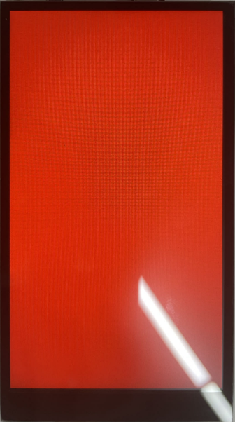
Image Displaying
Note: This interface is not supported by all modules. Please refer to the WIKI for specific supporting status.
Example (st7701s):
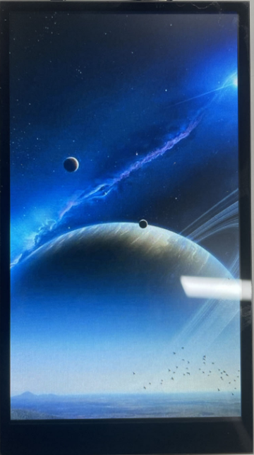
mipilcd.lcd_show_jpg("usr/background.jpeg", 0, 0)
The screen is displayed as follows:
FAQs
Screen Flickering
When initializing the display screen without writing any data, the phenomenon known as 'screen flickering' may occur. The main reasons for this may include:
The initial state of the display buffer: When you initialize the display but haven't written any data, the display buffer may contain random data, which can result in random pixels being displayed on the screen, also known as screen flickering. This is because most systems do not automatically clear the display buffer during initialization.
Power and signal issues: If the power supply to the display is unstable or if there is interference in the data signal, it can also cause screen flickering. This may require checking the quality of the power supply and signal lines.
Display driver program or hardware issues: If there are issues with the display driver program or if the display hardware malfunctions occurs, it can also cause screen flickering. For example, the driver program may not properly initialize the display hardware or there may be hardware malfunctions.
To resolve this issue, you can try clearing the display buffer immediately after initializing the display by setting all pixels to the same color (usually black or white). This should eliminate the screen flickering. If the problem still exists, you may need to check your power supply and signal lines or investigate if there are any issues with the display driver program and hardware.
Low Refresh Rate
There can be several reasons for a low refresh rate on an LCD, including:
- Hardware performance limitations: Limitations in memory or data bus bandwidth. Currently, the maximum SPI frequency for QuecPython series modules is 50 MHz, and most screens cannot adapt to such a high frequency, resulting in a lower refresh rate for larger screens.
- Driver program or operating system issues: The driver program or operating system may not be properly configured or optimized to fully utilize the hardware performance. For example, the driver program may not properly configure the display controller, or the operating system may not schedule graphics tasks correctly.
- Display settings issues: Display settings, such as resolution, may be too high and exceed the capabilities of the hardware or driver program. Please try lowering the resolution to see if it improves the refresh rate.
- Display controller or panel issues: The display controller or LCD panel itself may have performance limitations that prevent achieving a higher refresh rate.
- Signal interference or quality issues: If using long data cables or if the signal quality is poor, it can lead to a lower refresh rate. Please try replacing the data cables or improving the signal quality.
- Application issues: The running application may be consuming a significant amount of graphics resources, resulting in a lower refresh rate. Please try closing unnecessary applications or reducing the graphics demands of the application.
Screen Cannot Light Up
There can be various reasons why an LCD screen cannot light up. Here are some common possibilities:
- Power issues: LCD screens require a power supply, and if there are issues with the power supply, such as excessive or insufficient voltage, poor contact with the power line, or a faulty power adapter, it can prevent the LCD screen from lighting up.
- Interface issues: LCD screens are typically connected to the driver circuit or the main control board through some interface (e.g., MIPI, SPI). If these interfaces have unstable connections or if there are issues with the interface lines, the LCD screen may not work properly. When driving MIPI (due to hugh MIPI frequency), the LCD screen may not work properly if the connection line is too long or has folds.
- Driver issues: If there are issues with the driver program or if the main control board is not properly configured for the LCD screen parameters, the LCD screen may not be able to be lit up, such as incorrect settings for resolution, color depth, refresh rate, or bugs in the driver program.
- Hardware failure: The LCD screen itself may have hardware failures, such as damages on LCD panel, backlight, driver IC, or other electronic components. The LCD screen may fail to be lit up due to these issues.
- Signal issues: Signal issues such as damaged signal lines or poor signal quality (e.g., excessive noise, weak signal) can also prevent the LCD screen from displaying properly.
Touchscreen
In embedded devices, a touchscreen is a common input device used to replace a mouse or other pointing devices for interacting with and controlling the device's interface. It is typically a flat surface on which users can touch and slide their fingers to perform corresponding actions.
Types
Here are some common types of touchscreens, along with their working principles, characteristics, and applications:
- Resistive Touchscreen:
- Working Principle: A resistive touchscreen consists of two layers of resistive material. When touched, the two layers make electrical contact at the point of contact, causing a change in resistance. By measuring the change in resistance, the touchscreen controller can determine the touch position.
- Characteristics: Low cost, high durability, and can withstand various environmental factors such as dust and water. The disadvantage is its lower touch accuracy and support for single-touch only. Transparency and color reproduction may not be as good as other types.
- Applications: Commonly used in low-cost devices and industrial equipment, such as POS systems and industrial control panels.
- Capacitive Touchscreen:
- Working Principle: Capacitive touchscreens detect touch positions by measuring changes in capacitance on the screen. When a finger touches the screen, it causes a change in capacitance, which is detected as a touch event.
- Characteristics: High touch accuracy, support for multi-touch, good color reproduction and high transparency. The disadvantage is its relatively higher cost and limited touch input with only fingers or special styluses.
- Applications: Capacitive touchscreens are widely used in smartphones, tablets, and laptops.
- Infrared Touchscreen:
- Working Principle: Infrared touchscreens detect touch positions by measuring the interruption of infrared light caused by the touch. The screen edges are equipped with infrared emitters and receivers, and when a touch event occurs, it blocks some of the infrared light.
- Characteristics: Supports multi-touch and can be touched with any object. The downside is lower accuracy compared to capacitive and resistive touchscreens and susceptibility
- Applications: Infrared touchscreens are typically used in large display devices, such as interactive TVs, electronic whiteboards, and more..
- Surface Acoustic Wave (SAW) Touchscreen:
- Working Principle: SAW touchscreens use ultrasonic waves to detect touch positions. When you touch the screen, it absorbs or disrupts some of the ultrasonic waves, and by measuring this change, the touch location can be determined.
- Features: It has very high touch accuracy and excellent image quality, but it is sensitive to environmental changes, such as temperature, humidity, and liquid splashes, which can affect its performance.
- Applications: Commonly found in gaming devices and devices requiring high precision and high-quality images.
Each type of touchscreen has its advantages and suitable applications, and the choice of which type to use depends on specific application requirements.
Driver Block Diagram
The relationship between the MCU/CPU, driver IC, and interface is as follows:

Touch Controller: Also known as the main controller, it is the core component of the touchscreen system. It is responsible for receiving signals from the touchscreen sensor and converting these signals into understandable coordinate information. The touch controller can be a separate IC or a module integrated into a microprocessor or microcontroller.
Touch Sensor: This is the physical part of the touchscreen system, which can be a film or a glass panel. When we touch this sensor, it converts our touch actions into electrical signals and sends them to the touch controller.
Interface: This is the way the touch controller communicates with other components, such as microprocessors or microcontrollers. Common interface types include I2C, SPI, and USB etc.
Microprocessor or Microcontroller: It processes the data from the touch controller and translates this data into useful commands, such as moving the cursor or opening applications.
Therefore, the operation of this system can be simplified into the following steps:
Touch -> Touch Sensor -> Electrical Signal -> Touch Controller -> Data -> Interface -> Microprocessor or Microcontroller -> Commands
Compatibility Notes
For detailed interface description, please refer to [WIKI_Touch](TODO 链接).
The support status on QuecPython series modules is as follows:
| Name | Function | Interface | Driver | Datasheet |
|---|---|---|---|---|
| xpt2046 | Resistive Touch | SPI | tm1650.py | xpt2046.pdf |
| gt9xx | Capacitive Touch | I2C | gt9xx.py | gt9xx.pdf |
| cst816 | Capacitive Touch | I2C | cst816.py | cst816.pdf |
Calibrating the Touch Screen
In practical applications, resistive touch screens need to be calibrated before use, while capacitive touch screens are usually calibrated by the control chip and do not require additional calibration steps. The calibration algorithm for resistive touch screens is already integrated in the driver. During the calibration process, the screen will light up four points, and you need to touch them one by one to calibrate. The collected data will be compared, and if the error is too large, the calibration will fail and you need to touch again.
Calling the calibration function xtp2046.adjust() will start the calibration process on the screen. After the calibration is completed, the parameters will be saved in a file. The next time you initialize xtp2046, the calibration data will be read to avoid repeated calibration before each use.
Touch Screen Press
Whether it is a resistive or capacitive touch screen, the touch controller chip usually has an interrupt pin to notify touch events, and the level can be read through this pin interrupt. However, the signal provided by the touch controller is often less accurate than the judgment made by the program through the register. When creating a touch object, you need to pass in the interrupt pin number.
For resistive touch screens, the criterion for judging a press is that the pressure in the Z direction is greater than the configured threshold; for capacitive touch screens, it is judged that at least one touch point exists.
Touch Screen Rotation
The touch screen has 8 directions, just like the display screen. It is defined in the parameters when creating the touch object (x_inv, y_inv, xy_swap). The rotation is achieved through software calculation.
The resolution setting of the touch screen is also important because the rotation calculation of the touch screen depends on the width and height resolution of the touch screen. Improper settings will result in incorrect rotation effects.
Note:
When using a resistive touch screen, the resistance values in each direction may not be evenly distributed, which may cause inaccurate touch positions after rotation calculation. Therefore, it is recommended not to rotate the resistive touch screen after calibration.
Example
QuecPython has already adapted three touch drivers, which can be used directly.
Taking the touch screen (GT911) of the [Uranium EVB](TODO 链接) as an example:
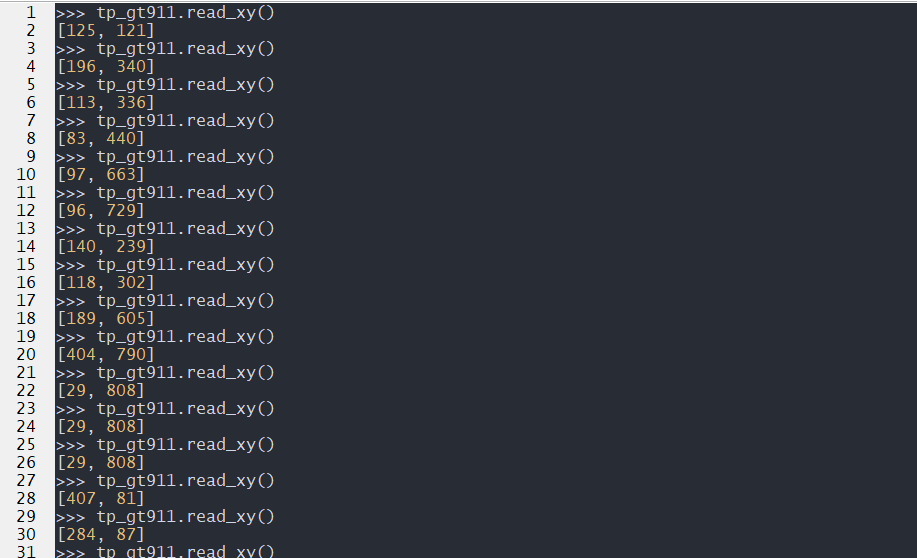
from tp import gt9xx
tp_gt911 = gt9xx(irq=40,reset=20)
tp_gt911.activate()
tp_gt911.init()
tp_gt911.read_xy()
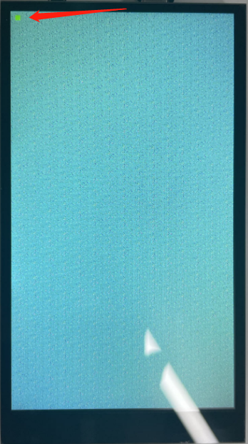
The effect is as follows:
Common Issues
Inaccurate Touch
Inaccurate touch may be caused by the following reasons:
- Calibration Issues: If the touch screen is not calibrated correctly or there are errors during the calibration process, the touch screen may not accurately recognize the touch position. In this case, you need to calibrate the touch screen.
- Driver Issues: If there are problems with the touch screen driver program, it may cause inaccurate touch positioning. In this case, you may need to update or fix the touch screen driver program.
- Hardware Issues: Hardware problems can also cause inaccurate touch. For example, the touch screen sensor may be damaged, or there may be connection issues between the touch screen and the controller.
- Electromagnetic Interference: In certain environments, electromagnetic interference may cause inaccurate touch positioning. This may require changing the device's operating environment or adding electromagnetic shielding measures.
- Software Issues: In some cases, issues with the application may affect the accuracy of touch. For example, some applications may not handle touch input correctly, resulting in deviation in touch positioning.
Touch Malfunction
There can be several reasons for touch screen malfunction:
- Hardware Failure: The touch screen itself or the hardware connected to it (such as the controller, data cables, etc.) may have failures, including physical damage, aging, poor contact, etc.
- Driver Issues: The touch screen driver software may have failures, such as defects in the driver program, compatibility issues, incorrect installation or update of the driver, etc.
- Software Conflict: In the operating system, other software or drivers may conflict with the touch screen driver.
- Power Issues: The power supply to the touch screen may be unstable or insufficient, which can cause touch screen malfunction.
- Environmental Factors: Extreme environmental conditions such as temperature, humidity, static electricity, etc., can also affect the normal operation of the touch screen.
Touch Response Delay
Several factors can cause touch response delay:
- Processor Overload: If the processor of the embedded device is busy processing a large number of tasks, it may not have enough resources to process touch input quickly, resulting in touch response delay.
- Software Issues: The driver program of the touch screen or operating system may have issues that cause delay in touch event processing. In addition, if the application running on the device is poorly designed or optimized, it may also cause touch response delay.
- Hardware Issues: If there are problems with the touch screen or its related hardware, it may cause touch response delay. For example, the touch screen sensor or controller may have performance issues.
- Communication Delay: In some embedded systems, there may be delays in data transmission between the touch screen and the processor, which can be caused by slow interface speed or poor quality of data cables, etc.
Digital Displays
Digital displays or LED dot matrix displays are common display solutions in embedded systems. This solution consumes fewer pins and memory resources compared to LCD screens, making it simpler to implement and suitable for applications that require single-digit or character displays, such as timers, counters, and status indicators.
Digital displays come in various types, including LED, LCD and VFD digital displays.
- LED Digital Displays
- Working Principle: LED digital displays are based on the principle of light emission when the PN junction of a light-emitting diode (LED) conducts. These displays typically consist of 7 or 14 LED segments, and they can display various numbers or characters by controlling the brightness of these segments using a controller.
- Features: LED digital displays are known for their high brightness, wide viewing angles, long lifespan, and excellent vibration resistance. However, they consume relatively higher power.
- Applications: LED digital displays are widely used in electronic devices and instruments such as digital watches, timers, calculators, and alarm clocks.
LCD Digital Displays
- Working Principle: LCD digital displays utilize the property of liquid crystal materials to change the transmission of light under the influence of an electric field. Typically, they consist of 7 or 14 LCD segments controlled by a controller to display various numbers or characters.
- Features: LCD digital displays are characterized by low power consumption, a soft display effect, and strong adaptability to environmental conditions. However, they have limited viewing angles and are sensitive to temperature changes.
- Applications: LCD digital displays find widespread use in portable and low-power electronic devices such as wristwatches, electronic dictionaries, and mobile phones.
VFD Digital Displays
- Working Principle: VFD digital displays generate light using the principle of gas discharge. These displays typically consist of 7 or 14 fluorescent emitters controlled by a controller to display various numbers or characters.
- Features: VFD digital displays are known for their high brightness, rich display colors, wide viewing angles, and fast response. However, they consume higher power and have a shorter lifespan compared to other types.
- Applications: VFD digital displays are commonly used in household appliances and entertainment devices such as televisions, DVD players, and stereo systems.
Driver Block Diagram
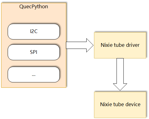
- Microcontroller (MCU): The microcontroller is the core of the system and is responsible for processing and executing all operations. It sends commands to the display driver IC through an interface based on the information to be displayed.
- Display Driver IC: The display driver IC (also known as a digital display driver IC) is an integrated circuit specifically designed to drive digital displays. It receives commands from the microcontroller and drives the digital display to display the corresponding numbers or characters based on these commands.
- Interface (SPI, I2C, etc.): The interface is the communication path that connects the microcontroller and the display driver IC. The microcontroller sends commands to the display driver IC through the interface.
- Digital Display: The digital display is the display device driven by the display driver IC. It displays the corresponding numbers or characters based on the commands from the display driver IC.
In a basic digital display system, the relationship between these components can be summarized in the following steps:
- The microcontroller generates commands based on the information to be displayed.
- The microcontroller sends the commands to the display driver IC through the interface.
- The display driver IC receives these commands and drives the digital tube to display the corresponding numbers or characters.
This is the working principle of a basic digital display system. Different digital display systems may have different specific implementations, but most systems follow this basic pattern.
Compatibility Information
The QuecPython series modules is compatible with the following device:
| Name | Function | Interface | Driver | Datasheet |
|---|---|---|---|---|
| TM1650 | LED driver control chip with keyboard scanning, supports 8-segment × 4 digits and 7-segment × 4 digits | I2C | tm1650.py | TM1650 |
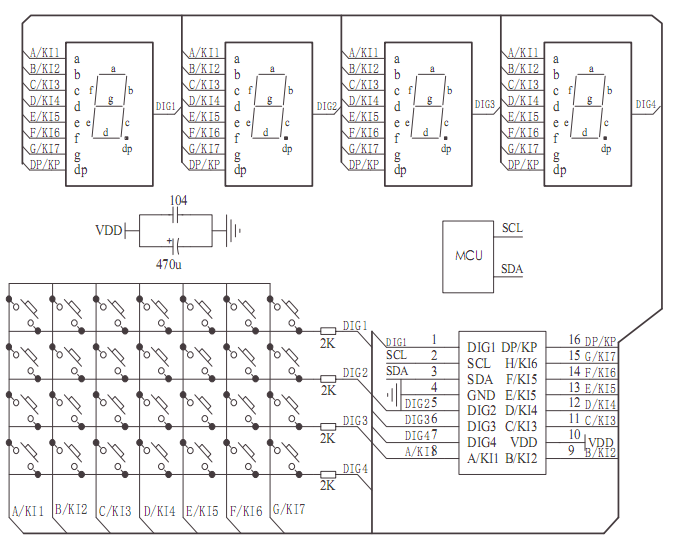
TM1650
TM1650 is a dedicated circuit for LED (light-emitting diode display) driver control with a keyboard scanning interface. It integrates MCU input/output control digital interface, data latch, LED driver, keyboard scanning, brightness adjustment, and other circuits.
It supports two display modes: 8-segment × 4 digits and 7-segment × 4 digits.
It can communicate with QuecPython series modules through I2C.
The tm1650 script has encapsulated the basic operations of TM1650, and users can directly call interfaces such as Tm1650.show_num, Tm1650.show_str, Tm1650.show_dp, etc. to display on the digital tube.
from usr.tm1650 import Tm1650
tube = Tm1650(Pin.GPIO13, Pin.GPIO12) #600U PIN60,PIN59
tube.on()
tube.all_show()
utime.sleep(1)
tube.clear_bit(3)
utime.sleep(1)
tube.all_clear()
utime.sleep(1)
tube.show_dp(3)
utime.sleep(1)
tube.show_str("PPJ")
utime.sleep(1)
tube.show_num(-537)
utime.sleep(1)
tube.show_num(8537)
utime.sleep(1)
tube.circulate_show("AbCdEFH")
Frequently Asked Questions
- The digital display is not lit up: This may be a power supply issue, such as poor contact of the power line or insufficient power supply voltage. It may also be a problem with the digital display itself, such as internal circuit damage. In addition, if a controller-driven digital display is used, there may be issues with the driver program or the hardware of the controller.
- The digital display does not display completely or displays incorrectly: This is usually a problem with the driver circuit or control program. For example, if the driver program does not set or update the display data correctly, it may result in display errors.
- The digital tube is flickering: If the digital tube is flickering unintentionally, it may be the reason of unstable power supply or the driver program issues. For example, if the power supply voltage is unstable, it may cause the brightness of the digital tube to constantly change, resulting in flickering. Additionally, if the driver program does not refresh the display data correctly, it may also cause the digital display to flicker.
- Uneven brightness or inconsistent color of the digital tube: This may be caused by the quality issues with the digital display itself or problems with the driver circuit. For example, if some LEDs of the digital display age unevenly, it may result in uneven brightness or inconsistent color.