


- 首页
-
产品中心
- 蜂窝模组
- 短距离模组
- 单板电脑
- 产品选型工具
-
EG915
-
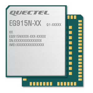


EG915N 系列是移远通信最新推出的 LTE Cat 1 无线通信模块,支持最大下行速率 10 Mbps 和最大上行速率5 Mbps,具有超高的性价比。同时,在封装上兼容移远通信 GSM/ GPRS M35 模块、LTE Cat M1/ Cat NB2/EGPRS BG95 系列模块、LTE Cat M1/ Cat NB1/ EGPRS BG96 模块、LTE Cat 1 EG91 系列模块和 LTE Cat 4 EG95 系列模块,实现不同网络间的无缝切换。
-
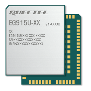

EG915U 系列是移远通信推出的 LTE Cat 1 无线通信模块,支持最大下行速率 10 Mbps 和最大上行速率 5 Mbps,具有超高性价比;同时在封装上兼容移远通信多网络制式 EG91 系列、EG95 系列、BG95 系列和 BG96模块,实现了 2G 网络和 4G 网络的无缝切换,以满足不同行业产品应用需求。 EG915U 系列包含 EG915U-CN、EG915U-EU、EG915U-EC 和 EG915U-LA 四个型号,满足不同国家和地区的频段覆盖。EG915U 系列采用镭雕工艺,具有外观精美、金属质感强、散热更好、信息不易抹除、更能适应自动化需求等优点。
-
-
EC200
-
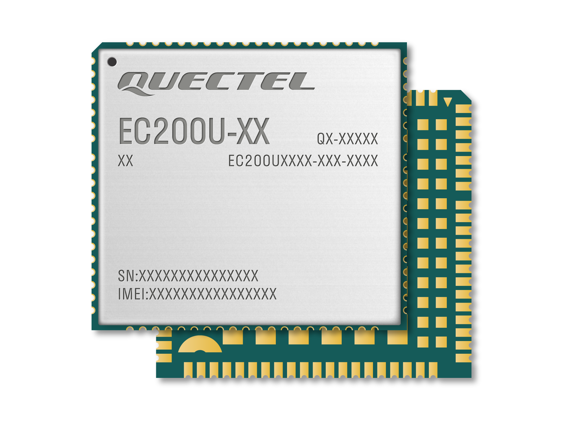
EC200U 系列是移远通信最新推出的 LTE Cat 1 无线通信模块,支持最大下行速率 10 Mbps 和最大上行速率 5 Mbps,具有超高性价比;同时在封装上兼容移远通信多网络制式 LTE Standard EC20-CE、EC20-CN、EC200S 系列、EC21 系列、 EG21-G 、EC25 系列和 EG25-G 模块,实现了兼容模块之间的切换。EC200U 系列 还支持标准的 Mini PCIe 封装,以满足不同行业产品应用需求。 EC200U 系列包含 EC200U-CN、EC200U-EU 和 EC200U-AU 三个型号,满足不同国家和地区的频段覆盖。EC200U 系列采用镭雕工艺,镭雕工艺具有外观更好看、金属质感强、散热更好、信息不容易被抹除、更能适应自动化需求等优点。
-
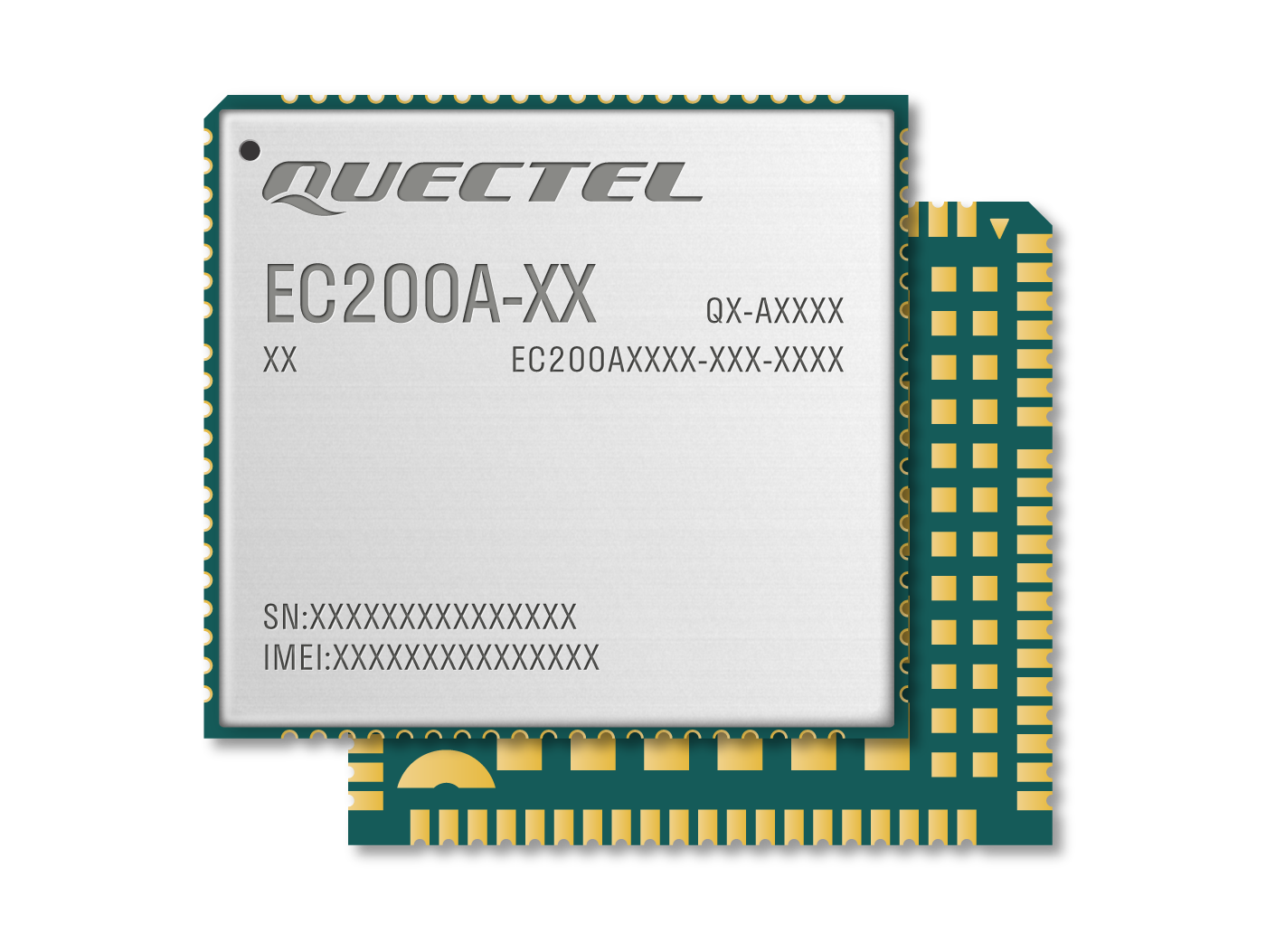
EC200A 系列是移远通信专为 M2M 和 IoT 领域设计的 LTE Cat 4 无线通信模块,采用 3GPP Rel-9 LTE 技术,支持最大下行速率 150 Mbps 和最大上行速率 50 Mbps。同时,EC200A 系列在封装上兼容移远通信的多网络制式LTE Standard EC25 系列、EC21 系列、EC20-CE、EG25-G、EC200D 系列、EC200U 系列、EC200N-CN 和 UMTS/HSPA+ UC200A-GL 模块,实现了从 3G 网络向 4G 网络的轻松平滑过渡。 EC200A 系列包含 4 个型号:EC200A-CN、EC200A-EU、EC200A-AU 和 EC200A-EL,满足不同国家和地区的频段覆盖;向后兼容现存的 GSM/GPRS/EDGE 网络,确保在缺乏 3G 和 4G 网络的偏远地区也能正常工作。模块采用镭雕工艺,具有外观精美、金属质感强、散热更好、信息不易抹除、更能适应自动化需求等优点。
-
-
EC600
-

EC600K-CN 是移远通信一款专为 M2M 和 IoT 领域而设计的 LTE Cat 1 bis 无线通信模块,支持最大下行速率10 Mbps 和最大上行速率 5 Mbps。同时,在封装上兼容移远通信 EC600M 系列、EC600E-CN、EC600N-CN、EC600G 系列 和 EC600U 系列模块。 EC600K-CN 采用镭雕工艺,具有外观更好看、金属质感强、散热更好、信息不容易被抹除、更能适应自动化需求等优点。
-
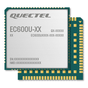
EC600U 系列是移远通信推出的 LTE Cat 1 无线通信模块,支持最大下行速率 10 Mbps 和最大上行速率 5 Mbps,具有超高性价比;同时在封装上兼容移远通信 LTE Standard EC600E-CN、EC600G 系列、EC600M 系列 和EC600N-CN 模块,实现了 2G 网络到 4G 网络之间的无缝切换,以满足不同行业产品应用需求。 EC600U 系列包含五个子型号:EC600U-CN、EC600U-EU、EC600U-EC、EC600U-CE 和 EC600U-LA。EC600U 系列依托现有 4G 网络,满足不同国家和地区的频段覆盖,能有效规避 2G/3G 退网带来的风险。具有超低功耗、低延迟和良好的移动性等特性,并且可支持语音通话。EC600U 系列采用镭雕工艺,镭雕工艺具有外观更好看、金属质感强、散热更好、信息不容易被抹除、更能适应自动化需求等优点。
-
-
EG912
-

EG912N-EN 是移远通信最新推出的 LTE450 Cat 1 无线通信模块,支持450 MHz,支持最大下行速率 10 Mbps 和最大上行速率5 Mbps,具有超高的性价比。同时,在封装上兼容移远通信 GSM/ GPRS M35 模块、LTE Cat M1/Cat NB2/ EGPRS BG95 系列模块、 LTE Cat M1/ Cat NB1/ EGPRS BG96 模块、LTE Cat 1 EG91 系列模块和 LTE Cat 4 EG95 系列模块,实现不同网络间的无缝切换。EG912N-EN 采用镭雕工艺,具有外观精美、金属质感强、散热更好、信息不易被抹除以及更能适应自动化需求等优点。
-

EG912U-GL是移远通信推出的 LTE Cat 1 无线通信模块,支持最大下行速率 10 Mbps 和最大上行速率 5 Mbps,具有超高性价比;同时在封装上兼容移远通信多网络制式 BG95 系列、BG96、 EG91 系列、EG95 系列、EG915U 系列模块,实现了 2G 网络和 4G 网络的无缝切换,以满足不同行业产品应用需求。 EG912U-GL 满足不同国家和地区的频段覆盖。采用镭雕工艺,具有外观精美、金属质感强、散热更好、信息不易抹除、更能适应自动化需求等优点。
-
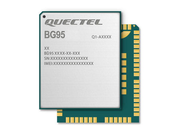
- BG95
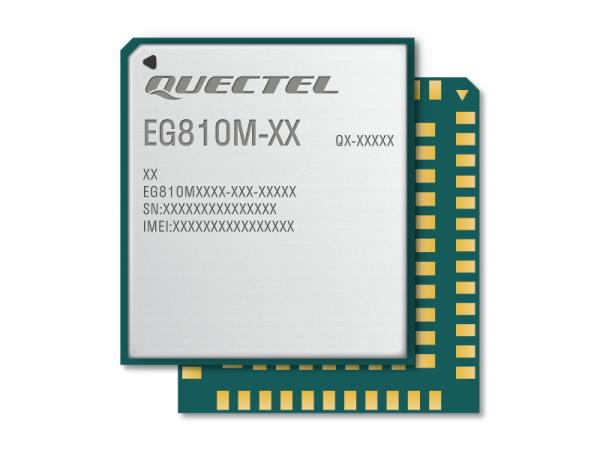
- EG810
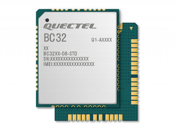
- BC32
- FCM360
- 解决方案
- 资源下载
-
文档中心
- 集中展示 QuecPython 开发资源,让开发更简单迅速
- QuecPython 文档中心
- QuecPi 文档中心
- 在线工具
- 在线商城
- 联系我们