
UART-Universal Asynchronous Receiver-Transmitter
An universal asynchronous receiver/transmitter (UART) is a hardware feature that processes communications (i.e. timing requirements and data frames) using widely adopted asynchronous serial communication interfaces such as RS232, RS422, and RS485. UART provides a widely adopted and inexpensive way to achieve full duplex or half duplex data exchange between different devices.
Basic knowledge
Each UART controller can configure parameters independently, including baud-rate, data bit length, bit queue, stop bit quantity and parity check. All regular UART controllers will be compatible with the device that supports UART of individual manufacturer.
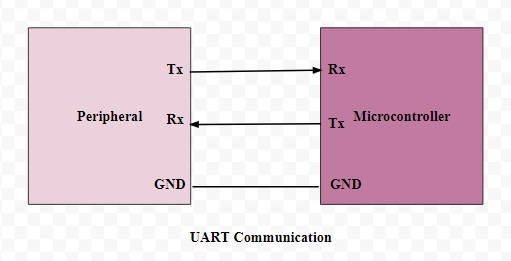
In UART communication, two UARTs communicate directly with each other. The transmitting UART converts parallel data from a controlling device like a CPU into serial form, transmits it in serial to the receiving UART, which then converts the serial data back into parallel data for the receiving device. Only two wires are needed to transmit data between two UARTs. Data flows from the Tx pin of the transmitting UART to the Rx pin of the receiving UART:
UARTs transmit data asynchronously, which means there is no clock signal to synchronize the output of bits from the transmitting UART to the sampling of bits by the receiving UART. Instead of a clock signal, the transmitting UART adds start and stop bits to the data packet being transferred. These bits define the beginning and end of the data packet so the receiving UART knows when to start reading the bits.
When the receiving UART detects a start bit, it starts to read the incoming bits at a specific frequency known as the baud-rate. Baud-rate is a measure of the speed of data transfer, expressed in bits per second (bps). Both UARTs must operate at about the same baud-rate. The baud-rate between the transmitting and receiving UARTs can only differ by about 10% before the timing of bits gets too far off.
Both UARTs must also must be configured to transmit and receive the same data packet structure.
How UART works

The UART that is going to transmit data receives the data from a data bus. The data bus is used to send data to the UART by another device like a CPU, memory, or micro-controller. Data is transferred from the data bus to the transmitting UART in parallel form. After the transmitting UART gets the parallel data from the data bus, it adds a start bit, a parity bit, and a stop bit, creating the data packet. Next, the data packet is output serially, bit by bit at the Tx pin. The receiving UART reads the data packet bit by bit at its Rx pin. The receiving UART then converts the data back into parallel form and removes the start bit, parity bit, and stop bits. Finally, the receiving UART transfers the data packet in parallel to the data bus on the receiving end:
UART Block Diagram
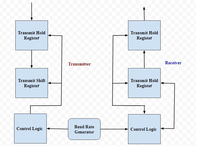
The UART block diagram consists of two components namely the transmitter & receiver that is shown below. The transmitter section includes three blocks namely transmit hold register, shift register and also control logic. Likewise, the receiver section includes a receive hold register, shift register, and control logic. These two sections are commonly provided by a baud-rate-generator. This generator is used for generating the speed when the transmitter section & receiver section has to transmit or receive the data.
The hold register in the transmitter comprises the data-byte to be transmitted. The shift registers in transmitter and receiver move the bits to the right or left till a byte of data is transmitted or received. A read (or) write control logic is used for telling when to read or write.
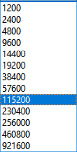
The baud-rate-generator among the transmitter and the receiver generates the speed that ranges from 110 bps to 230400 bps. Typically, the baud rates of micro-controllers are 9600 to 115200.
Frame structure
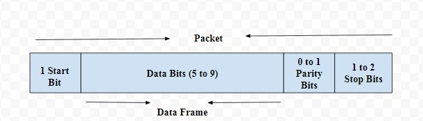
UART transmitted data is organized into packets. Each packet contains 1 start bit, 5 to 9 data bits (depending on the UART), an optional parity bit, and 1 or 2 stop bits:
IDLE STATUS
High level. Which means there is no data transmission in current path.
START BIT
The UART data transmission line is normally held at a high voltage level when it’s not transmitting data. To start the transfer of data, the transmitting UART pulls the transmission line from high to low for one clock cycle. When the receiving UART detects the high to low voltage transition, it begins reading the bits in the data frame at the frequency of the baud rate.
DATA FRAME
The data frame contains the actual data being transferred. It can be 5 bits up to 8 bits long if a parity bit is used. If no parity bit is used, the data frame can be 9 bits long. In most cases, the data is sent with the least significant bit first.
PARITY
Parity describes the evenness or oddness of a number. The parity bit is a way for the receiving UART to tell if any data has changed during transmission. Bits can be changed by electromagnetic radiation, mismatched baud rates, or long distance data transfers. After the receiving UART reads the data frame, it counts the number of bits with a value of 1 and checks if the total is an even or odd number. If the parity bit is a 0 (even parity), the 1 bits in the data frame should total to an even number. If the parity bit is a 1 (odd parity), the 1 bits in the data frame should total to an odd number. When the parity bit matches the data, the UART knows that the transmission was free of errors. But if the parity bit is a 0, and the total is odd; or the parity bit is a 1, and the total is even, the UART knows that bits in the data frame have changed.
STOP BITS
To signal the end of the data packet, the sending UART drives the data transmission line from a low voltage to a high voltage for at least two bit durations.
Baud-rate
The frequency modulated in signal in line, expressed in bits per second (bps) or b/s. The clock signal with fixed frequency will vibrate and send one bit data signal each clock period.
It is demanded by UART communication that the both sides should be aligned in baud-rate. However, since the UART is asynchronous, that is to say there is not a clock line to connect each other. As a result, both of them will modulate one equivalent baud-rate according to internal clock theoretically. However, due to the inevitable error in HW itself, the actual baud-rate will not be aligned with theoretical value. While it is demanded that the error in baud-rate of both sides can differ only about 10%, otherwise, the error codes will be read by receiver.
Hardware flow control
Both sides with any communication protocol will be allocated with buffer of limited storage space to receive the data from other side. Once the other party sends data too fast, and processing speed of itself is slow, there may be a serious situation that the buffer is full and cannot be processed, and even data loss.
In this situation, the flow control is extremely important: When the receiver is unable to burden more date, it will notify the transmitter to stop sending data. After that, if it is capable to accept, it will notify transmitter again to transmit data.
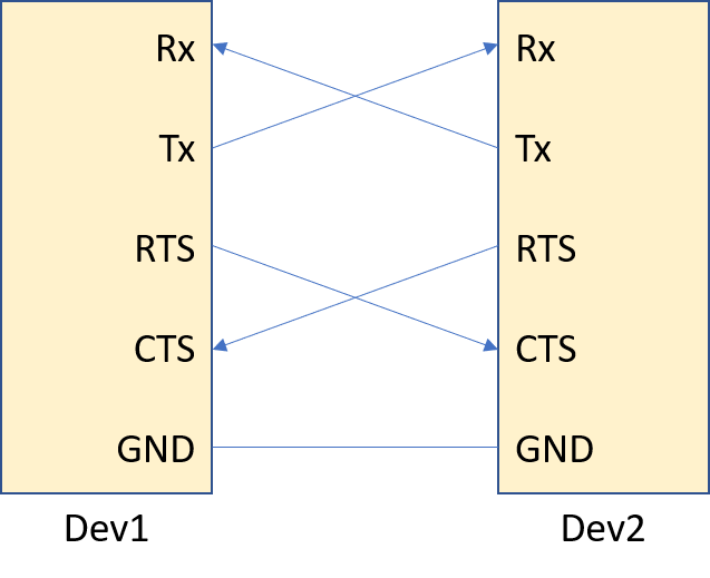
See above diagram for UART interface of HW flow control pin. Compared with former, two pins namely RTS and CTS are added.
RTS
Output capability, which connects to the CTS of other side. When the RTS of its is pulled high, it will notify the UART of other side to stop transmitting data. Once the RTS goes back to low, it will notify the other side to transmit data again.
CTS
Input capability, which connects to the RTS of other party. When the CTS of its own side detects the high, it will stop transmitting data. Once the low level is detected by CTS of its, it is valid to transmit data.
FIFO
As one kind of basic data structures, the synchronous and asynchronous FIFO (First-In, First-Out) can be implemented in HW and SW. (In this chapter, it will introduce synchronous FIFO only)
SW FIFO
- Definition: The FIFO implemented by programming data structure in SW, like array and linked list.
- Application: Task scheduling in operation system, data packet processing in network or any scenario that needs queue.
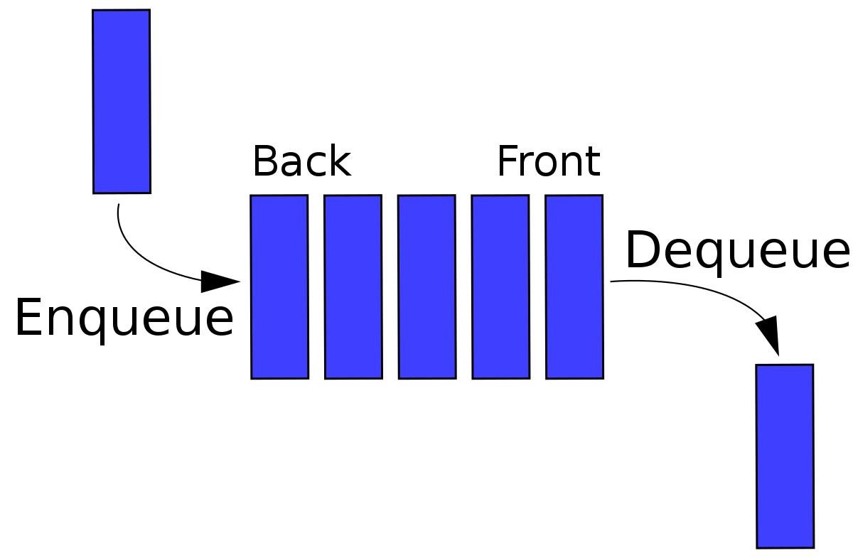
- Operation: Enqueue (add to the back of the queue) and dequeue (remove from the front of the queue)
- Advantage: Flexible, which can adjust the size or implement priority queue easily.
- Disadvantage: Since it is implemented in SW, it will not as fast as HW FIFO.
Implementation
As for SW FIFO, the ringbuffer is widely used.
Compared with linear buffer, there is no need to allocate memory frequently. The repeated usage in memory will allow us to carry out more tasks with fewer memory blocks. Meanwhile, it will be more convenient and safer to manage memory. Normally, the ringbuffer will be used when reading and writing buffer frequently.
The ringbuffer refers to buffer made by a logic ring with head and tail connected instead of that in physical. Since the memory space is made by linear structure, the ringbuffer is still one section of memory with certain length of FIFO actually. Moreover, it has the function of mutually exclusive access of communication processes to the buffer.
Principle
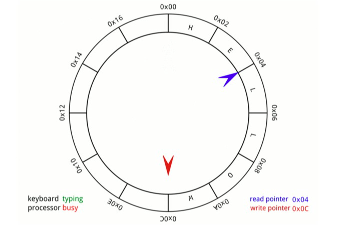
The ringbuffer is endowed with fixed length, as a result, it just needs to adjust the location of head, write pointer and tail pointer that point at this buffer instead of deleting all data when deploying it. The write pointer will point at head pointer first of all (The start location of ringbuffer) and the data will be saved in write pointer. In addition, the location of write pointer will move back for one certain length when one data is stored each time. Once the write pointer points at the tail pointer, it will re-point at head pointer and cover the original location till all data is stored. The benefit of ringbuffer lies in that it will reduce memory allocation, decrease system cost and memory fragment quantity, facilitating long and stable running.
Generally, one ringbuffer is composed by one consecutive memory space and 4 pointers.
head Pointer: Point to the start address of memory
tail Pointer: Point to the end address of memory
read pointer: Point at the start location where stores data in memory
write pointer: Point at the end location where stores data in memory
After applying for memory and pointer definition, see following content on ringbuffer illustration and application.
- This memory length will be displayed as: Len = tail-head
- The read pointer refers to the start location of reading data. After reading N data, it is needed to move offset with N length. Also, it is necessary to store the data with addlen into ringbuffer. If it meets addlen + write pointer > tail, the write pointer will store data with len1 = tail - write pointer and go back to head. The remaining data with len2 = addlen - len1 will be stored from head and overwrite the former data.
- The write pointer refers to the start location of writing data. After storing N data, it is needed to move offset with N length. When it is needed to read data with addlen from ringbuffer, if it meets addlen + read pointer > tail, the read pointer will store data with len1 = tail - read pointer and go back to head. The remaining data with len2 = addlen - len1 will be read from head till the end.
HW FIFO
- Definition: The FIFO implemented in HW, especially in digital circuit
- Application: Commonly used in communication interface such as UART and SPI for data buffer.
- Implementation: It will be implemented via register array or RAM with dual-interface. Moreover, it is endowed with read pointer and write pointer.
- Advantage: Fast speed, which can operate with other HW modules at the same time. Moreover, it can provide efficient data flow.
- Disadvantage: Fixed size, which is not as flexible as SW FIFO
Currently, the HW FIFO is used by QuecPython Series for data buffer and cross-asynchronous data transmission based on HW circuit.
Synchronous FIFO
- Definition: The read and write of synchronous FIFO are operated in the same clock.
- Principle: The same clock signal will be used to control the data read and write. Once the new data is written, the write pointer will move; When the data is read, the read pointer will move as well.
- Application: Commonly used in data flow buffer in the same clock domain.
Write: The FIFO can store or write data in each location of clock according to w_en signal till the data is full. Meanwhile, the write pointer will increment when each data is written into FIFO memory.
Read: It will extract or read data from FIFO in each location of clock according to rd_en signal till the data is empty. Meanwhile, the read pointer will increment when each data is read from FIFO memory.
The read and write pointers will be generated by counting write and read requests in inner FIFO, which indicate the read and write address of memory. To be specific, the write pointer will point at the next address to be written while the read pointer points at the next address to be read. Similarly, the write request will increment write pointer and the read request will increment read pointer.
The module with FIFO will output empty and full signal to indicate its state, which are displayed as fifo_full and fifo_empty. The "fifo_full" means the fifo memory is full and not allowed to write data. While the "fifo_empty" indicates that there is no next valid data could be read in memory.
Reason to generate fifo_full and fifi_empty in synchronous FIFO
When resetting, the read and write pointer in FIFO will turn to zero. In this situation, when pulling up the fifo_empty, it allows to write without reading, once the new data is written, the fifo_empty will be pulled down and allowed to read data. Under the circumstance that the write pointer of fifo points at fifi_depth-1, the write operation will make the write pointer turned to zero and pulled the fifo_full high.
When the write pointer is equivalent to read pointer, the fifo will be either full or empty. Therefore, it is needed to discriminate above two conditions.
- FIFO_FULL
The FIFO_FULL is triggered by write: when the write facilitates the equivalence between read pointer and write pointer in next clock, the FIFO_full will occur. That is to say the write pointer catches up with read pointer with an assistance of write. That is, the write pointer is one circle behind the read pointer.
- FIFO_EMPTY
The FIFO_empty is triggered by read: when the read facilitates the equivalence between read pointer and write pointer in next clock, the FIFO_empty will occur. That is to say the read pointer catches up with write pointer with an assistance of read.
FIFO Asynchronous FIFO
- Definition: The read and write of asynchronous FIFO will be operated in different clock domain.
- Working principle: Two independent clocks will be used to write and read respectively. However, it demands special design to ensure the intactness and synchronization of data that crosses clock domain.
- Application: Data transmission of two clock domains with different operation frequency or different sources.
DMA
The DMA, acronym of Direct Memory Access, allows peripherals such as Hard disk, audio interface and network adaptor to exchange data with system memory without going through CPU. This mechanism can improve data transmission efficiency heavily since it allows device to transmit data without occupying CPU time.
Characteristics
The DMA and CPU are not parallel since there exists only one main memory. As a result, it is unavailable for both CPU and DMA to access main memory at the same time. The high efficiency lies in that the on-spot protection and recovery are not needed.
The DMA transmission itself will occupy system resource such as IO or RAM instead of interrupting program. Thus, once it is demanded for CPU to access to same IO or RAM, it will take extremely long time till the DMA transmission is done and the resource is released. From the perspective of SW, it is similar with interrupting program. However, the essence is quite different since the CPU works continuously without switching task. Finally, there is no need to protect on-spot.
Moreover, if the CPU owns certain cache and the DMA transmission speed is adequate, the SW will not detect that the program is halted even if the same RAM is accessed.
Operating process
- Inquiry and Authorize :
- When a peripheral such as hard disk controller shall exchange data with memory, it will deliver one DMA request (DRQ as well) to DMA controller.
- Once the request is received by DMA controller, it will execute data transmission when the system bus is in idle state.
- Once prepared, the DMA controller will send a DMA Grant (DACK) to CPU, which will make the CPU paused after the current command is executed and release bus control.
- Data transmission:
- The DMA controller will take charge bus and carry out data transmission. It can transmit in single byte or a patch of data in accordance with actual setting.
- The DMA controller will update source and target addresses and count the bytes that still need to be transmitted.
- In stage of data transmission, the CPU will be inactive or "isolated" since it does not take part in it.
- Accomplished transmission:
- Once all data has been transmitted by DMA controller, it will delete DMA Grant signal.
- The DMA controller will transmit one interrupt signal (Under the circumstance that it has been set) to CPU to notify that the data transmission is accomplished. Therefore, the CPU can retrieve to process data or execute other tasks.
- Interrupt service:
- If the interrupt that has been implemented in DMA is enabled, the CPU will receive one interrupt request after the data transmission is done.
- The CPU will call corresponding interrupt service routine (ISR) to process tasks after transmission such as post-data processing, error checking and so on.
- Reset and prepare next DMA:
- The DMA controller will reset its state and prepare responding next DMA request.
Characteristic and Application
Characteristics
- Simplicity: The HW and programming in UART communication will be simpler since the UART is implemented in micro-controller or other processor. Therefore, no extra chip is needed in terms of HW.
- Unnecessary clock sync: Since the UART is async, there is no need to share the same clock signal when transmitting and receiving, reducing the complexity in HW design.
- Flexibility: In UART communication, it is available to adjust data bit length, stop bit quantity and parity check according to various demands.
- Reliability: Although it is not equipped with BF (Bug Fix) in UART, the Parity check is capable to detect error to some extent.
- Limitation: To some extent, the UART communication speed is restricted. In addition, the faster communication speed, the more error will occur as well. Meanwhile, it is also demanded in distance. For long distance, the RS-422 and RS-485 will be used probably.
Application:
Embedded system : The UART will be widely used in micro-controllers or other lower HW devices such as sensor, SD card and GPS module.
Serial communication : The UART can be applied to RS232, RS422 and RS485 to connect with printer, modem and display.
Computer HW: In preliminary computer HW, the UART will be used in interface of peripherals such as mouse and keyboard.
Telecommunication device: In wireless communication and telecommunication device, the UART will communicate with SIM card and other devices.
BT module: In BT module, the UART will communicate with host device.
IoT device: In IoT device, the UART will communicate among devices with low speed.
Supported situation
For support of individual QuecPython module, see machine.UART.
Data flow
It will introduce UART data flow based on QuecPython EC600U module
Data flow in Transmitting data
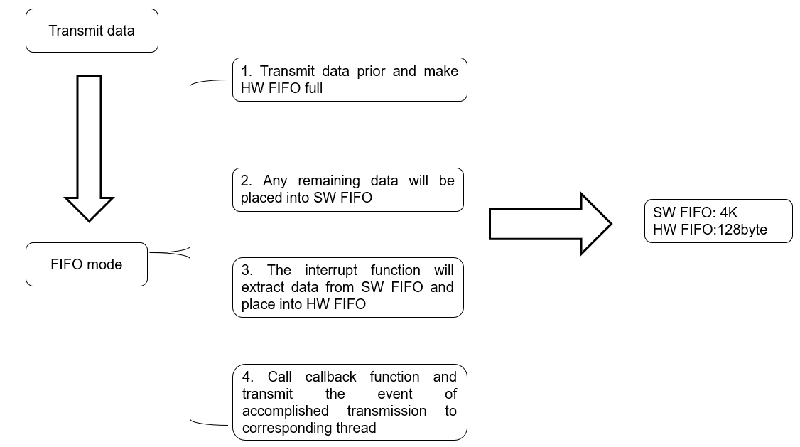
Under the circumstance that the data is invisible in FIFO more than 500ms, the data transmission will be ended.
TX communication: Transmit data -Transmit event once data transmission is complete-trigger interrupt-trigger callback function and transmit event to corresponding thread and process- corresponding thread triggers callback function defined by user.
Only one type can trigger interrupt: TX_COMPLETE.
Flow in receiving data
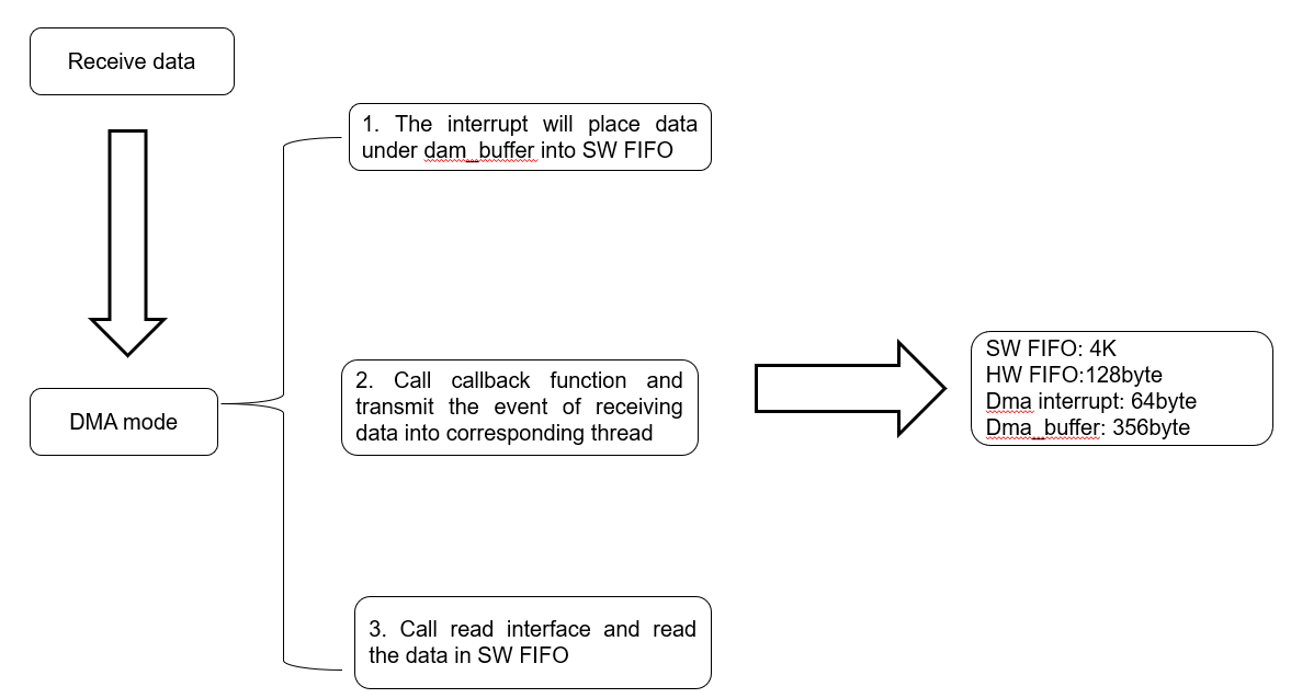
In terms of RX communication, there exist two interrupts -dma (64 bytes are received) OT (In condition that less than 64 bytes are received without triggering dma interrupt for 40ms)
Two kinds will trigger interrupt: RX_ARRIVED and RX_OVERFLOW
In condition that the SW FIFO is full, issues such as data overflow and data loss will occur if it receives more data. Meanwhile, the RX_OVERFLOW event will be reported. Therefore, it is necessary to process the received data, otherwise, it will occur issue such as data loss and incomplete data. For data transmission with large quantity, the HW flow control can be considered.
Rx communication: Receive data for 64 bytes or OT -> trigger interrupt-> trigger callback function and send event to corresponding thread and process-> corresponding thread triggers callback function defined by user.
Function illustration
In this chapter, it will illustrate how to communicate between QuecPython Series and other UART devices based on function of UART driver program and data type.
For specific API, see machine.UART.
Create object
The UART communication parameters will be configured in this step, including baud-rate, data bit, parity check bit, stop bit and flow control.
class machine.UART(UART.UARTn, baudrate, databits, parity, stopbits, flowctl
About parameters introduction and pin mapping, see machine.UART.
When creating objects, please pay attention to following aspects.
1. Set baud-rate: The baud-rate indicates the bits quantity can be received or transmitted via UART interface per second. Normally, the baud-rate will be accomplished via corresponding generator in UART. Kindly reminder: the baud-rate in Tx and Rx shall be aligned, otherwise, it may lead to failed communication.
2. Set data bit: The data bit quantity will determine how many bits can be involved in each character, which will be varied in 5,6,7, 8 and 9 data bits (among which, the 8 data bits will be used commonly). Similar with baud-rate, the data bit quantity in Tx and Rx shall be aligned.
3. Set stop bit: The stop bit refers to one or two bits after each character that identifies the end of the character. 1 or 2 stop bits will be set commonly. Please note the stop bit quantity in Tx and Rx shall be aligned.
4. Set parity check: The Parity check detects the possible error in data transmission, including three kinds: No check, even check and odd check. In addition, the Parity check setting in Tx and Rx shall be aligned.
Transmit data
Prepare data to be transmitted and call uart.write() as well. Subsequently, this function will copy data into Tx ringbuffer immediately or there exists available space and exit. Under the circumstance that there is available space in Tx FIFO buffer, the ISR (Interrupt Service Routine) will move the data from Tx ringbuffer to Tx FIFO buffer in backstage.
msg = "This is a test string"
uart.write(msg)
About API, see machine.UART.write
Receive data
Once the data is received by UART and saved into Rx buffer, the uart.read() can be applied to search. In addition, it is available to check the approachable bytes in Rx buffer via calling uart.any() before reading data.
msg_len = uart.any()
msg = uart.read(msg_len)
In terms of receiving data, following aspects shall be noted:
1. Buffer management: It is vital to manage buffer correctly. If data is not read before being overwritten by new data, there might be a data loss. Therefore, ensure data are read and processed in time before it's overwritten.
2. Concurrent and multiple threads: If concurrent and multiple threads are supported, please take thread security into consideration when receiving data by UART. I.e., it is possible that the lock and other sync mechanisms will be used to avoid multiple threads access to buffer at the same time.
3. Data format: The received data format shall be aligned with the settings in Tx, including data coding (ASCII, UTF-8 and binary), data bit quantity, start bit, stop bit and parity check bit.
For API introduction, please refer to machine.UART.read.
Interrupt
Set serial data callback. Once the data is received, this callback will be executed. Meanwhile, the specific data counts will be returned.
See following example.
from machine import UART
uart1 = UART(UART.UART1, 115200, 8, 0, 1, 0)

def uart_call(para):
    print(para)
uart1.set_callback(uart_call)
For API introduction, please refer to machine.UART.setCallback
To avoid executing interrupt for a long time, it is needed to notify other threads to read serial port data by sending semaphore in callback.
RS485 control
Control 485 communication direction: Pull up/down dedicated GPIO to notify 485 communication direction before and after transmitting data by serial port.
For API introduction, please refer to machine.UART.control_485.
Applications
| Cases | Description |
|---|---|
| Basic Tx/Rx | Configure UART setting and read and write via UART1. It will read data in a method of callback |
| External GNSS | By decrypting the GNGGA, GNRMC and GPGSV in raw GNSS data packet read from external GNSS by UART to get positioning info. |
| RS485application | Set UART driver programm in half duplex to communicate via RS485 interface |
| Power meter chip | Take power meter chip as an example: read and write corresponding parameter via UART to get power data or execute other controlling commands. |
Basic Tx/Rx
In terms of communication module, one simplified method is provided by QuecPython to carry out UART communication. For real-time application or scenario needs deal with UART info effectively, it is suggested to read UART via callback function.
Before that, it is necessary to learn about UART QuecPython Interface, see machine.UART
Procedure
Initialize UART
from machine import UART
# Initialize UART1
uart1 = UART(UART.UART1, 115200, 8, 0, 1, 0)
Write into UART Transmit data to UART
uart1.write('Hello UART1')Read data via callback function
When deploying callback function in UART, one IRQ (Interrupt request) will be set to monitor UART event such as data reception. Under the circumstance that these events are triggered, relevant callback function will be executed.
Please make sure the callback function should be as short as possible so as to reduce the interference to other system tasks. Meanwhile, it is a must to read data immediately when arrival to avoid data loss owing to FIFO overflow underlying.
def uart_callback(arg):
    _queue.put(para[2])

# Set interrupt
uart1.set_callback(uart_callback)
Example
import _thread
import utime
from machine import UART
from queue import Queue

class Example_uart(object):
    def __init__(self, no=UART.UART2, bate=115200, data_bits=8, parity=0, stop_bits=1, flow_control=0):
        self.uart = UART(no, bate, data_bits, parity, stop_bits, flow_control)
        self._queue = Queue(5)
        _thread.start_new_thread(self.handler_thread, ())
        self.uart.set_callback(self.callback)


    def callback(self, para):
        print("call para:{}".format(para))
        if(0 == para[0]):
            self._queue.put(para[2])

    def uartWrite(self, msg):
        print("write msg:{}".format(msg))
        self.uart.write(msg)

    def uartRead(self, len):
        msg = self.uart.read(len)
        utf8_msg = msg.decode()
        print("UartRead msg: {}".format(utf8_msg))
        return utf8_msg

    def uartWrite_test(self):
        for i in range(10):
            write_msg = "Hello count={}".format(i)
            self.uartWrite(write_msg)
            utime.sleep(1)

    def handler_thread(self):
        while True:
            recv_len = self._queue.get()
            self.uartRead(recv_len)

if __name__ == "__main__":
    uart_test = Example_uart()
    uart_test.uartWrite_test()
External GNSS
In embedded system, it is common that the GNSS (Global Navigation Satellite System) receiver will be connected by UART, including GPS, GLONASS, Galileo, BeiDou and so on. Moreover, this connection allows system to decrypt GNSS data to acquire current location, speed, time and other relevant info.
Nowadays, some QuecPython modules are integrated with external GNSS and series of interfaces are provided. For specific, please refer to gnss_wiki in detail. Thus, it is available for user to acquire data via these above interfaces, including whether the module positioning is a success, coordinates, UTC time, positioning mode of GPS module, satellite quantity, visible satellite quantity, Azimuth, ground speed and Geoid Height. Currently, the data acquired is originated from raw GNSS data packet read by serial port, including GNGGA, GNRMC and GPGSV.
In this chapter, it will introduce based on L76K.
Procedure
Confirm serial port
Please confirm which serial port of the module that the L76K is connected as well as deployed baud-rate. In this case, the L76K is connected to the UART2 of the module and the baud-rate is default 9600bps (Above info can be queried via L76K manual)
Instantiate object
>>> from gnss import GnssGetData
>>> gnss_obj = GnssGetData(2, 9600, 8, 0, 1, 0)
Read and decrypt data
Based on following interface, the user can read and decrypt data directly.
>>> gnss_obj.read_gnss_data()
822
Operations as reading raw data and decrypting are implemented in inner interface. Finally, only data length read by serial port is returned. If the user desires to read the raw data decrypted, it is available to call following interface.
>>> data = gnss_obj.getOriginalData()
>>> print(data)
$GNGGA,063957.000,3802.01852,N,11437.92027,E,1,13,1.2,129.2,M,-15.7,M,,*62
$GNGLL,3802.01852,N,11437.92027,E,063957.000,A,A*40
$GNGSA,A,3,01,03,06,14,30,194,,,,,,,1.8,1.2,1.4,1*00
$GNGSA,A,3,13,23,33,38,40,43,59,,,,,,1.8,1.2,1.4,4*3C
$GPGSV,3,1,11,01,38,044,12,03,44,101,24,06,30,233,31,14,79,184,34,0*6F
$GPGSV,3,2,11,17,58,319,,19,40,296,04,21,11,051,,30,14,202,34,0*67
$GPGSV,3,3,11,194,44,156,27,195,68,074,,199,44,160,25,0*6F
$BDGSV,3,1,11,03,44,186,,07,83,121,05,10,65,309,,13,37,206,31,0*79
$BDGSV,3,2,11,23,21,181,31,28,69,354,14,33,24,115,27,38,65,190,30,0*7A
$BDGSV,3,3,11,40,70,093,18,43,28,065,15,59,38,143,29,0*44
$GNRMC,063957.000,A,3802.01852,N,11437.92027,E,0.69,168.35,260422,,,A,V*0B
$GNVTG,168.35,T,,M,0.69,N,1.29,K,A*2F
$GNZDA,063957.000,26,04,2022,00,00*44
$GPTXT,01,01,01,ANTENNA OPEN*25
Confirm whether it is a success
If the user just concerns about the positioned coordinates and its validity, following interface can be applied. If it returns 1, which means the positioning is successful and effective.
>>> gnss_obj.isFix()
1
Acquire coordinate info
Call next interface to acquire positioning coordinate.
>>> gnss_obj.getLocation()
(114.6320045, 'E', 38.033642, 'N')
What is acquired by above interface are longitude and latitude based on WGS-84 coordinate system, which is not allowed to get location via Amap, Tencent and Baidu. Please convert it as the coordinates.
Example
The following codes illustrates how to get position coordinate via gnss module.
import utime
from gnss import GnssGetData


def main():
    gnss_obj = GnssGetData(2, 9600, 8, 0, 1, 0)
    while True:
        try:
            read_size = gnss_obj.read_gnss_data()
        except Exception:
            print('Data exception and decryption error!')
            data = gnss_obj.getOriginalData()
            print('===============================================')
            print(data)
            print('===============================================')
            utime.sleep(2)
            continue

        if read_size > 0:
            if gnss_obj.isFix():
                coordinate = gnss_obj.getLocation()
                longitude = coordinate[0]
                latitude = coordinate[2]
                print('Succeed in positioning and current longitude and latitude are displayed:({}, {})'.format(longitude, latitude))
                utime.sleep(10)
            else:
                print('In positioning, please wait...')
                utime.sleep(2)
        else:
            print('Unable to get position data...')
            utime.sleep(2)


if __name__ == '__main__':
    main()
RS-485 application
The RS-485 is capable to work in half-duplex mode, which means it can either transmit or receive data only at the same time. In order to switch, one GPIO (General-Purpose Input/Output) will be used normally.
This GPIO will be targeted at the line for "direction control". When the line is HIGH, the RS-485 driver will be activated and transmits data. While low, the driver will be disabled and allows other devices to transmit data in bus. Then the local device will receive it.
Before sending data, the GPIO will be set as HIGH and transmits data afterwards. Once former step is accomplished, the GPIO will be set as LOW and switched to Rx mode.
QuecPython supports the transfer of GPIO control directions in the UART. The uart.control_485 can be applied to control 485 communication direction. The designated GPIO will be pulled up/down to indicate the communication direction of 485 before and after transmitting data via serial interface.
Direction is set as 1: it will be pulled from low to high before transmitting data and pulled from high to low after transmitting data via serial interface.
Direction is set as 0: it will be pulled from high to low before transmitting data and pulled from low to high after transmitting data via serial interface.
See specific example as follows
from machine import UART
uart1 = UART(UART.UART1, 115200, 8, 0, 1, 0)
uart1.control_485(UART.GPIO24, 1)
Power meter chip
In this chapter, it will illustrate how to read and write the chip parameters, acquire power data and execute other commands via UART based on HLW8110 Power meter chip.
For specific, please refer to HLW8110 Datasheet.
For raw codes, please refer to hlw8110.py
HLW8110 Description:
- Targeted to single-phase application, the HLW8110 is a high precision power metering IC with CMOS.
- It can measure line voltage and current, and calculate active power. Additionally, it can measure apparent power and Power Factor.
- HLW8110 has three detection channels of ∑-Δ type and one high-precision power meter kernel, including current detection channels A and B, and voltage detection channels. A channel and B channel can be used for current detection at the same time. B-channel can be used for current detection or leakage detection. The individual input channel supports flexible PGA settings. Therefore, the HLW8110 can adapt to different sensors such as CT and Shunt with low resistor.
- HLW8110 is capable to access to on-chip register via UART interface.
- HLW8112 contains two configurable pulse output pins, which can be used to acquire over-current, over-voltage, zero-crossing voltage or current detection and leakage detection through INT1 and INT2 pins.
- HLW8110 power metering IC uses 3.3V or 5.0V power supply with Internal Frequency Oscillator. HLW8110 is encapsulated with SOP8 or SSOP16.
Typical Application
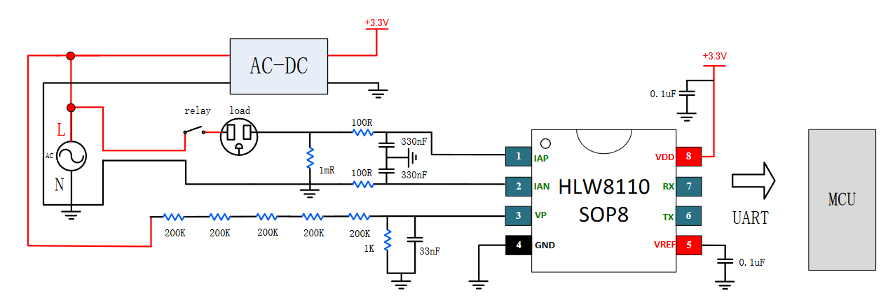
Operating procedure
Analog measurement:
The HLW8110 will connect with external current sensor and voltage sampling circuit to acquire the analog signal of current and voltage.
Analog to Digital channel:
The analog signal will be converted into digital signal via ADC.Digital process:
The inner chip will process the digital signal converted by ADC and calculate the active power, reactive power and Power Factor.
Output:
The HLW8110 will provide pulse output related to measured parameter via specialized output pin. In addition, these pulses can be read by external micro-controller and processed further.
Communication
The UART communication format of HLW8110 is as follows:
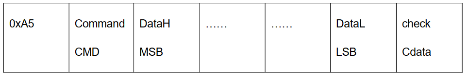
- UART command register is the same as SPI, and it's also an 8 bit wide register. For the read-write operation, the command register bit7 is used to determine whether the type of data transmission operation is read operation or write operation. For special command operations, bit7-0 of the command register is fixed to 0xEA.
- UART data transmission of HLW8110: Read operation is sent by slave and write operation is sent by host. If the register address corresponds to a multi-byte register, the highest valid byte is passed first.
- UART data verification mode of HLW8110: read operation is sent by slave and write operation is sent by host.
- Calculating methods of calibration data are as follows: Check data Cdata [7:0] = A5 + CMD [7:0] + DATAn [7:0] +... + DATA1 [7:0], which adds CMD and data, discards carry, and the final result is reversed bit by bit.
| Command name | Command Register | Data | Description |
|---|---|---|---|
| Read command | {0[bit7],REG_ADR[bit6:bit0]} | RDATA | Read data from registers with REG_ADR [6:0] The highest bit is 0, which means reading data to registers. |
| Write command | {1[bit7],REG_ADR[bit6:bit0]} | WDATA | Write data from registers with REG_ADR [6:0] The highest bit is 0, which means writing data to registers |
| Write enable command | 0xEA | 0xE5 | Enable write operation |
| Write protection command | 0xEA | 0xDC | Close write operation |
| Channel A select | 0xEA | 0x5A | Current channel A setting command specifies the current signal used to calculate apparent power, power factor, phase angle, instantaneous apparent power and active power overload as channel A |
| Channel B select | 0xEA | 0xA5 | Current channel B setting command specifies the current signal used to calculate apparent power, power factor, phase angle, instantaneous apparent power and active power overload as channel B |
| Reset instruct | 0xEA | 0x96 | Reset instruct, chip reset after receiving instruction |
In stage of UART operation, if the Rx keeps LOW or the HIGH surpasses 9.15ms, it is available to reset UART module. Normally, it will not rewrite the register value that has been written into inner chip. When conducting UART communication between MCU and HLW8110/HLW8112, please try reset UART module if it occurs exception in receiving data.
Test
Initialize and configure UART
Initialize UART and corresponding read/write register and reset interface
class Hlw8110_uart(Hlw8110):
    def __init__(self, uart_n, databits = 8, flowctl = 0):
        self.uart = UART(uart_n, 9600, databits, 1, 1, flowctl) #Fixed 9600 baudrate and EVEN are used in hlw8110
        super().__init__(self)

    def read_reg(self,reg):
        '''
        Read register
        :param reg: Register to be read
        :return: Success:Read data
                 Failure:Empty list
        '''
        #Transmit bytes of reading commands
        self.uart.write(bytearray([0xA5, reg]))
        check_data = 0xa5 + reg
        #determine whether any data is not read by uart
        while 1:
            msglen = self.uart.any()
            if msglen:
                #Read data
                r_data = list(self.uart.read(msglen))
                #Verify data
                for i in range(msglen-1):
                    check_data += r_data[i]
                check_data = ~check_data & 0xff
                if check_data == r_data[-1]:
                    return r_data[:-1]
                else:
                    return []

    def write_reg(self, reg, w_data):
        '''
        Write register
        :param cmd: Command to be written
        :param w_data: Data to be written, the list or tuple with a length of 2
        :return: 0:Success
        '''
        cmd = reg | 0x80        #{1[bit7],REG_ADR[bit6:bit0]}
        #Enable write operation 0xA5 0xEA 0XE5  Verify
        self.uart.write(bytearray([0xA5,0xEA,0xE5,0x8B]))
        #Write into register
        check_data = ~(0xA5 + cmd + w_data[0] + w_data[1]) & 0xff
        w_data = bytearray([0xA5, cmd, w_data[0], w_data[1],check_data])
        self.uart.write(w_data)
        #Disable write operation 0xA5 0xEA 0XDC Verify
        self.uart.write(bytearray([0xA5, 0xEA, 0XDC, 0x94]))
        return 0

    def reset(self):
        '''
        Reset command 0xA5 0xEA 0X96 Verify
        '''
        self.uart.write(bytearray([0xA5, 0xEA, 0X96, 0xDA]))
Read current:
Read register 0x70: Get current RMS Conversion Coefficient
Read register 0x2A: Get Channel A current RMS
def read_i(self):
    '''
    Read current RMS register and current RMS conversion coefficient. The specific current is relevant to the connected circuit, it is not necessary to calculate in this interface.
    :return: measure normally:(current RMS register and current RMS conversion coefficient)
    		No valid data:(0,0)
    '''
    #Alternating current or Direct current
    cur_type = self._child.read_reg(self.EMUCON_REG)
    if len(cur_type) != 2:
    	return (0,0)
    else:
    	cur_type = cur_type[1] & (1<<5)

    # Read current RMS conversion coefficient
    ic_read = self._child.read_reg(self.RMSIAC_REG)  # 16-bit unsigned number
    if len(ic_read) != 2:
    	return (0,0)
    ic_data = (ic_read[0]<<8) +ic_read[1]

    #Read current RSM register
    current_read = self._child.read_reg(self.RMSIA_REG)  # 24-bit signed number
    if len(current_read) != 3:
    	return (0,0)
    current_data = (current_read[0]<<16) + (current_read[1]<<8) + current_read[2]
    if cur_type:        #Direct current,
    	# When measuring direct current, the MSB is 1, which indicates two's supplement. However, the absolute value shall be needed.
    	if current_data & 0x800000:     #The MSB is 1, which indicates two's supplement. However, the absolute value shall be needed.
    		current_data = ~(current_data & 0x7fffff - 1)
    		return (current_data,ic_data)
    	else:
    		return (current_data,ic_data)
    else:               #Alternating current
    	if current_data & 0x800000:     #The MSB is 1, whihc indicates the data is 0.
    		return (0,ic_data)
    	else:
    		return (current_data,ic_data)
Read voltage
Read register 0x72: Get voltage RMS conversion coefficient
Read register 0x26: Get voltage RMS
def read_u(self):
    '''
    Read voltage RMS register and voltage RMS conversion coefficient.It is not necessary to calculate in this interface
    :return: measure normally:(voltage RMS register and voltage RMS conversion coefficient)
    		 No valid data:(0,0)
    '''
    # Alternating current or Direct current
    cur_type = self._child.read_reg(self.EMUCON_REG)
    if len(cur_type) != 2:
    	return (0,0)
    else:
    	cur_type = cur_type[1] & (1 << 4)
    # Read voltage RMS conversion coefficient
    uc_read = self._child.read_reg(self.RMSUC_REG)  # 16-bit unsigned number
    if len(uc_read) != 2:
    	return (0,0)
    uc_data = (uc_read[0] << 8) + uc_read[1]

    # Read voltage RMS register
    voltage_read = self._child.read_reg(self.RMSU_REG)  # 24-bit signed number
    if len(voltage_read) != 3:
    	return (0,0)
    voltage_data = (voltage_read[0] << 16) + (voltage_read[1] << 8) + voltage_read[2]
    if cur_type:  # Direct current
    	# When measuring direct current, the MSB is 1, which indicates two's supplement. However, the absolute value shall be needed.
    	if voltage_data & 0x800000:  # The MSB is 1, which indicates two's supplement. However, the absolute value shall be needed.
    		voltage_data = ~(voltage_data & 0x7fffff - 1)
    		return (voltage_data, uc_data)
    	else:
    		return (voltage_data, uc_data)
    else:  # Alternating current
    	if voltage_data & 0x800000:  # The MSB is 1, which indicates the data is 0.
    		return (0, uc_data)
    	else:
    		return (voltage_data, uc_data)
Read active power
Read register 0x73: Get active power RMS conversion coefficient
Read register 0x28: Get active power
def read_power(self):
    '''
    Read active power and active power conversion coefficient
    :return: Measure normally:(active power and active power conversion coefficient)
    		 No valid data:(0,0)
    '''
    # Read active power coversion coefficient
    pc_read = self._child.read_reg(self.POWER_PAC_REG)  # 16-bit unsigned number
    if len(pc_read) != 2:
    	return (0,0)
    pc_read = (pc_read[0] << 8) + pc_read[1]

    # Read active power register
    power_read = self._child.read_reg(self.POWER_PA)  # 32-bit signed number
    if len(power_read) != 4:
    	return (0,0)
    power_data = (power_read[0] << 24) + (power_read[1] << 16) + (power_read[2] << 8) + power_read[3]
    if power_data & 0x80000000:  # Two's complement, the MSB is sign bit
    	power_data = ~(power_data & 0x7fffffff - 1)
    	return (power_data, pc_read)
    else:
    	return (power_data, pc_read)
Notes
1. Select baud-rate: When setting baud-rate in UART, Please make sure the baud-rate in receiver and transmitter is aligned. The data transmission speed and system clock frequency shall be taken into consideration when selecting specific baud-rate. Do remember the high baud-rate may not only improve data transmission speed but also error codes.
2. Set data format: The data format in UART communication, including data bit, Parity check bit and stop bit, shall be aligned in receiver and transmitter. Normally, 8 data bits, no parity check and 1 stop bit (8N1) will be set.
3. Buffer management: When receiving data via UART, one Rx buffer will be used to store data normally. Therefore, It is needed to ensure the buffer is large enough to avoid data overflow and loss. In addition, the read and write in buffer shall be synchronized to avoid conflict in terms of situation with multiple tasks.
4. Flow control: In condition of high-speed data transmission or restricted processing capability, it is needed to control flow via HW or SW for sake of data loss.
5. Interrupt management: The interrupt will be used to receive or transmit data in UART. However, please ensure the ISR should be as short as possible to reduce the interference to other system tasks. Generally, the ISR will receive data from UART or transmit data to UART and move data to buffer or extract data from buffer as well.
6. Concurrent and multiple threads environment: When deploying UART in concurrent or multiple threads environment, it is needed to protect relevant resources based on semaphore and mutex, preventing data chaos when the UART is accessed by multiple tasks.
7. Power and GND: In embedded system, there will be multiple power levels and GND normally. Thus, it is necessary to ensure the power wire is connected to GND wire properly to avoid communication failure or device damage.
8. Error Processing: Such issues as frame, parity check and data overflow will occur in UART communication, Therefore, it is vital to design adequate error processing mechanism to solve or report these errors.
9. Physical interface: The UART device will be connected by different physical interfaces such as RS-232, RS-485 and TTL. Thus, please guarantee the correct interface level and connection.
10. Device driver and operation system compatibility: In embedded operation system, it is necessary to make sure the UART device driver is compatible with operation system. However, it is also important to compile or modify device driver in accordance with specific operation system and HW platform.
11. Real-Time: For embedded system, it should satisfy certain real-time demand. Thus, it is considerate to consider the impact of UART communication on the real-time of the system such as interrupt response time and data handling time.
12. Power consumption: In embedded system powered by battery, the power consumption of UART communication shall take into consideration. I.e., when the system is in low power consumption, it is needed to close UART device or set it as low power consumption probably.
Common issues and errors
As a simple and direct communication protocol, it may occur various issues in actual scenario for UART. See following common issues and investigation.
1. Receive data improperly or fails to receive data
It might be originated from several reasons, including wrong baud-rate, HW connection, interrupt processing and buffer overflow. See next investigation steps.
- Check whether the baud-rate in Tx and Rx is aligned. If it isn't, which may cause error in receiving data.
- Check HW connection: please make sure the proper connection in Tx, Rx and GND lines.
- If interrupt processing is used, please guarantee that it can process the received data properly and retain all data.
- Check Rx buffer. The unduly small space or slow race in processing will lead to data loss. Thus, it is suggested to enlarge buffer size or optimize processing.
2. Send data incorrectly or fails to send data
It might be originated from several reasons, including HW connection, Tx buffer and Tx program. See next investigation steps.
- Check HW connection: please make sure the proper connection in Tx, Rx and GND lines.
- Check Tx buffer and Tx program: please make sure the data to be transmitted will be placed into buffer properly. While the Tx program can read data from the buffer and transmit properly.
3. Communication distance
The communication distance on UART is restricted: unduly long communication distance may lead to signal attenuation, influencing data reception. If it is needed to communicate via longer distance, differential signal standard such as RS-422 or RS-485 shall be deployed.
4. Interference
In EMI environment, the UART communication may be influenced heavily. If possible, try reduce EMI via shielding wire or reduce noise and EMI via capacitance filter. If extremely huge interference, the differential signal standard or optoelectronic isolator shall be used instead.
When investigating error, it is available to observe UART signal via logic analyzer or oscillator, which can do a favor in tracing issue. While in SW, it is available to observe and analyze the running state of program via corresponding debugging tool.