
Power Management
Overview of Power Management
With the development of SoC technology, power management technology is also constantly innovating. Nowadays, SoC generally uses PMU (Power Management Unit) for power supply, and its design goals are generally are as follows:
Multi-level power supply requirements: As shown in the figure below, SoC often includes IP with different functionalities and voltage domains. As SoC becomes more complex and includes more IPs, a single SoC implements functionalities such as CPU, RF, camera, DDR control, peripherals, etc. Multiple functionalities and IP also bring the need for multi-level power supply. At the same time, in order to meet the low power consumption requirements, SoC is usually divided into multiple power domains, and different power domains can be independently powered on and off to achieve more flexible power consumption control.
Typical SoC Architecture Diagram:
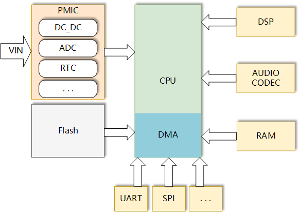
Energy saving and extending battery life: Efficient power management and control can be achieved according to different application scenarios and load requirements. For example, by dynamically adjusting power supply voltage and current parameters to adapt to different load requirements, battery usage efficiency and lifespan can be improved.
Protecting system safety and stability: Key parameters such as battery level, power temperature, voltage, and current can be monitored to ensure system safety and stability. For example, in the case of low or high battery level, excessive or insufficient current, the power management IC chip will automatically control and protect the power system to prevent damage or failure caused by power issues.
Providing multiple functionalities and interfaces: In addition to basic power management functionalities, PMU often integrates other functionalities such as ADC, CODEC, PWM, temperature monitoring, LED driver, RTC, etc. These functionalities can work together with the power management of PMIC itself to provide flexible and diversified power management solutions for different applications. They can also interact with the CPU through communication interfaces to enrich the functionality of SoC.
Improving system efficiency and performance: By using efficient DC-DC converters and sleep mode, system energy loss and power consumption can be reduced, thereby improving system efficiency and performance.
The typical power supply system and internal power management unit of a SOC chip are shown in the following figure:
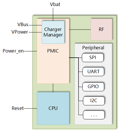
As shown in the figure, in the typical power supply system of SoC, the PMIC simultaneously supplies power to IP cores with different functionalities and also manages power-on and charging considerations. In addition to the input/output of power supply, the PMIC often integrates clock circuits, RTC circuits, various analog IPs (such as ADC and temperature sensors, and some PMICs integrate audio CODECs). How does the PMIC utilize its various functionalities for power management? In the following sections, we will start with the PMIC and introduce its composition and implementation of power management.
Introduction to PMU
PMU (Power Management Unit) is a highly integrated power management solution for portable applications. It integrates multiple discrete power management chips, such as low-dropout linear regulators (LDOs) and DC-DC converters, into the power management unit of a cellphone, which enables higher power conversion efficiency, lower power consumption, fewer components, and smaller board-level space, resulting in lower cost.
The PMU of a SoC processor generally requires the following features:
1. Multi-level power supply: External power chips are needed to provide multi-level power or apply higher current to a certain level of power. This is because SoC processors usually require independent power supply for their core, I/O devices, and storage units, and these units often have different requirements for voltage, current, frequency, etc.
2. State control: Provide dedicated control signals to the outside, and set the state of these control signals through PMU control registers to control the overall power state of the SoC. When some basic interface signals of the PMU (such as system power-on, system reset, power status indication, etc.) change, the state of the SoC processor will change accordingly.
The PMU consists of internal DC-DC converters, PMU registers, etc., and provides power supply for the SOC's processor, PLL, DDR, image unit, etc. At the same time, the PMU also controls the external power supply system through the Power Management Bus (PMBus).
Some basic functionalities of the PMU are as follows:
- Control power on/off and timing of power on/off
- LDO & DC-DC switch control
- CPU voltage & clock frequency adjustment
- Thermal mitigation
- Analog input ADC
- GPIO
- Charging
- RTC
- Watchdog
- CODEC
- Power management
Different PMUs of different SoCs may have different functionalities. Among the above functionalities, control of power on/off, thermal mitigation, GPIO, charging management, RTC, and low power management are more relevant to users. We will focus on these functionalities in the following chapters, and the power management will be covered in a dedicated chapter (Power Consumption Management).
Glossary
Before introducing PMIC, let's first understand some commonly used functionalities or technologies in power management:
1. Power Management Integrated Circuit (PMIC)
PMIC is the abreviation for Power Management IC, which is highly integrated. It encapsulates multiple output power into a single chip, making it more efficient and smaller in size for multi-power supply applications.
2. Power Management Unit (PMU)
PMU is a highly integrated power management solution for portable applications. It integrates multiple discrete power management chips, such as low-dropout linear regulators (LDOs) and DC-DC converters, into the PMU. This enables higher power conversion efficiency, lower power consumption, fewer components, and smaller board-level space, resulting in lower cost.
In most cases, PMU is equivalent to PMIC, but here the external power supply chip for SoC is called PMIC, and the internal power management unit for SoC is called PMU.
3. DC-DC
DC-DC refers to a direct current to direct current circuit, which broadly encompasses all power supplies with both input and output as direct current. LDO mentioned later is also one type of DC-DC. Here the DC-DC actually refers to one of the most typical implementations of DC-DC: the switch-mode constant current source. The DC-DC used in cellular baseband is generally a BUCK circuit. Depending on the application, it may have some special features, such as:
DVC_BUCK_DC-DC Circuit: Supplies power to the CPU, with strong load capacity and DVC (Dynamic Voltage Control) feature, allowing for dynamic voltage adjustment to achieve energy-saving purposes.
APT_BUCK_DC-DC Circuit: Supplies power to the radio frequency (RF) and power amplifier (PA), with strong load capacity and APT (Average Power Tracking) feature to reduce RF power consumption.
From the purpose, it is clear that DC-DC excels in handling large loads. In addition to load capacity, it also has the advantages of a wide input range and high conversion efficiency. Compared to LDO, its disadvantages include a complex structure, poor load response, significant ripple, and it is not suitable for supplying power to circuits sensitive to noise.
4. LDO
LDO stands for Low-Dropout Regulator, which is a linear power supply that can only perform voltage reduction. It has a weaker load capacity but offers a simple structure, low cost, and is suitable for large-scale deployment. Moreover, it produces low noise, has a fast load response, making it the best choice for analog circuits that are sensitive to noise.
In cellular baseband applications, LDOs are generally used to supply power to various discrete devices or peripherals (such as RTC circuits, GPIO, UART, etc.), which do not have high load requirements. LDOs are convenient for implementing low-noise circuits in multiple voltage domains.
5. RTC
RTC (Real-Time Clock) is a clock that provides precise real-time information to humans or serves as a precise time reference for electronic systems. Real-time clock chips usually use high-precision crystal oscillators as clock sources (normally for cellular modules, the adapted crystal oscillator frequency is 32768 Hz, which can achieve the highest timing accuracy). Some RTCs continue to operate even when the CPU is shut down, as the PMIC (Power Management Integrated Circuit) maintains power to the RTC circuitry.
In summary, we have introduced common functions and technologies frequently encountered in power management. Modern PMICs often employ these technologies to achieve their power management goals. Specific hardware connections, functions, and implementation methods will be described in the next chapter.
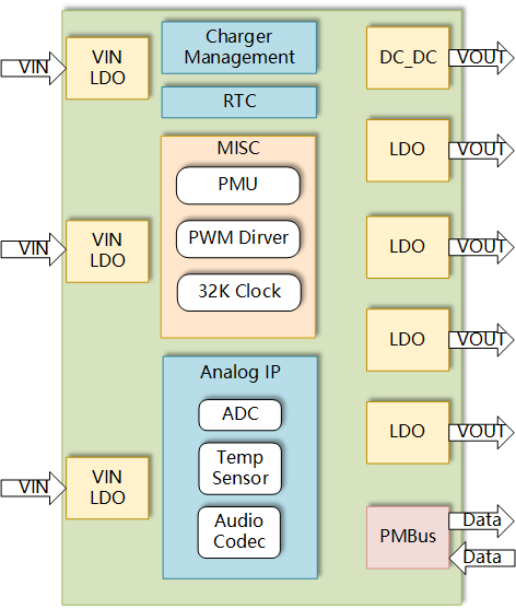
PMU Hardware Diagram
The internal typical hardware diagram of PMU is as follows:
In a typical SoC power supply system, the hardware connection of PMIC/PMU is generally as shown in the following figure:
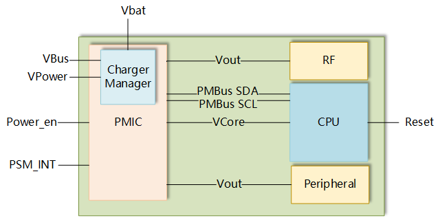
As can be seen, besides the power input and output, the main external connection pins of PMU are as follows:
1. power_en: Generally, it is the power key of the module. When the interrupt on this pin is triggered, the PMIC actively changes the power state of the SoC and supplies power to the CPU, triggering the boot behavior of the entire SoC. In the boot state, this pin interrupt is still available and can be bound to corresponding behaviors at the application layer.
2. PMBus: PMBus is a low-cost two-wire interface that is an extension of the SMBus standard and is based on the I2C protocol. Since PMBus is an extension of the SMBus protocol, it shares most of its physical layer and bus operation modes. However, PMBus defines a set of specific commands and data structures required for power control and management components.
PMBus is based on the I2C protocol and only requires two mandatory pins (SDA and SCL), so it has the advantages of low cost and strong scalability. In cellular modules, PMBus is often used as the communication protocol between PMIC and other devices (some modules, such as EC21, use the SPMI protocol). This allows the PMIC to control and monitor the power status of the entire module. At the same time, the CPU can also use PMBus to rewrite the PMU's registers, thereby achieving control of the power status at the application layer.
In addition, some sensor circuits of the cellular module (generally ADC and temperature sensors) are laid out on the PMU. When the CPU needs data from these sensors, the corresponding registers of the PMU are accessed through PMBus.
3. PSM_INT: The wake-up pin for PSM. It only works when the module enters PSM. It is generally supported by cellular modules that support PSM.
The concept of PSM is explained in Power Consumption Management
With the hardware configuration described above, PMU in cellular modules can realize functionalities such as power management, waking up from PSM sleep, voltage detection, and temperature detection. In the following sections, we will introduce the specific functionalities, implementation details, and usages of PMU.
Introduction to PMU's Main Functions
Powerkey and Reset
The pins used to control the power state of the module are the powerkey and reset pins. Although both of them are used to control the power state of the module, there are some differences in hardware connection and triggering principles. We will compare and introduce them below.
Hardware Connection and Power On/Off Principle of Powerkey
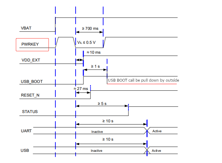
The powerkey is used to control the power on/off of the module. This button is connected to the PMIC. When the module is powered on, the PMIC is powered, but it does not supply power to the CPU. When the powerkey is pressed, the PMIC starts to supply power to the CPU and the program starts to run. In the bootloader stage, the powerkey's button detection program performs debounce processing and long-press judgment on the power key. When the powerkey is long pressed and reach the debounce threshold, the program continues to run and completes the boot process.
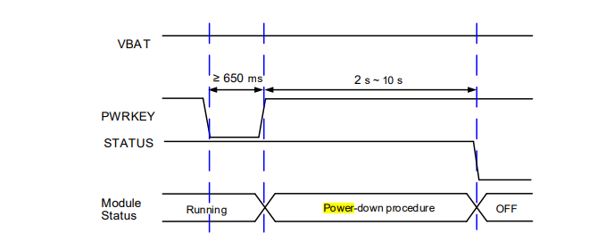
In the power-on state, long pressing the powerkey will trigger a shutdown. At this time, the CPU will receive an interrupt generated by the operation of long press of the powerkey and actively call the shutdown command, operating the PMIC to power off and change the power state of the module.
Power-On Timing Diagram:
Power-Off Timing Diagram:
Implementation of Power-On by Long Pressing the Powerkey
Check the powerkey for pin level and debounce in the bootloader. Since ISR cannot be used in the bootloader, most of the debounce is done by polling the powerkey status, and the PMIC is operated to shut down the module if the duration of the low level is less than the debounce time threshold.
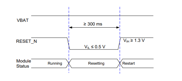
Hardware Connection and Restart Principle of Reset
Unlike the powerkey, RESET is generally directly connected to the CPU, and its triggering does not involve the PMIC. It only resets the CPU, returns the interrupt vector table to bootrom, and then starts execution from bootrom.
Reset Timing Diagram:
Customizing Short Press and Long Press of Powerkey
Customizing the short press and long press functions of the powerkey is actually button detection. The implementation method is to start a timer in the interrupt when the button is pressed, and stop the timer in the interrupt when the button is released. If the timer has not expired and is stopped by the interrupt triggered by the powerkey release, it is judged as a short press. If there is no interrupt triggered by the release until timeout, it is judged as a long press. The timeout of the timer is the threshold that defines the short press and long press.
Usage of configuring custom powerkey functions: class PowerKey - PowerKey Callback and Registration
Example code for customizing short press/long press of powerkey:
from misc import PowerKey
import osTimer

class Pwrkey(object):
    def __init__(self, time_threshold):
        self.pk = PowerKey()
        self.time_threshold = time_threshold
        self.timer = osTimer()
        self.is_long_press = 0
        self.pk.powerKeyEventRegister(self.pwk_callback)

    def long_press_cb(self):
        print('powerkey long press.')

    def short_press_cb(self):
        print('powerkey short press.')

    def pwk_timer_cb(self, arg):
        self.is_long_press = 1

    def pwk_callback(self, status):
        if status == 0:
            print('powerkey release.')
            self.timer.stop()
            if self.is_long_press:
                self.long_press_cb();
            else:
                self.short_press_cb();

        elif status == 1:
            print('powerkey press.')
            self.is_long_press = 0
            self.timer.start(self.time_threshold, 0, self.pwk_timer_cb)


if __name__ == "__main__":
    pwrkey = Pwrkey(1000)
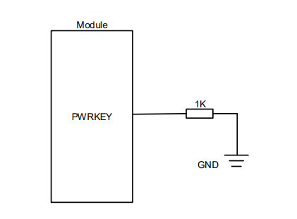
Implementation of Power-On Auto-Start Function
If you need to implement a power-on auto-start function without considering power-off, you can directly pull down the Powerkey to ground, and it is recommended to use a pull-down resistor of not more than 1 kΩ.
Power-on Auto Start Typical Design Circuit:
PSM_INT
Overview of PSM_INT
PSM_INT is a pin on the PMIC, and its feature is that it can still respond and trigger module wake-up while in PSM. However, please note that in shutdown mode, this pin is generally invalid. In other words, PSM_INT is a wake-up source that is only effective in PSM mode.
Principle of PSM_INT
For EC200U, EG91xU and BG95 series modules: On PMIC, when entering PSM, the interrupt for this pin is enabled by default. When triggered, it will wake the module up from PSM.
Usage
For EC200U, EG91xU and BG95 series modules: PSM_INT is typically enabled by default when entering PSM mode. It has a fixed pin level and triggering conditions. When the module enters PSM, PSM_INT will trigger directly.
GPIO Level Control During Sleep
GPIO Hardware Overview
In most cases, GPIO pins of the cellular module are connected to the CPU, but their power supply comes from one or more LDOs on the PMIC. This kind of GPIOs can work properly under two conditions:
- The CPU enables the GPIO (usually by writing to the corresponding GPIO registers. If the GPIO is used as an input pin, ensuring that GPIO interrupts are enabled).
- The PMIC maintains power to the GPIO.
If either of the above conditions is not met, it can lead to GPIO misbehavior. Therefore, it's important to pay special attention to the GPIO pin level cahnges during sleep.
However, please note that some PMICs with abundant resources may directly provide GPIO pins. These GPIOs do not require CPU control but are powered and controlled directly by the PMIC. The functionality of these GPIOs in sleep mode depends entirely on the PMIC. A detailed explanation of the behaviors of these two t GPIOs during sleep in the next chapter.
GPIO Pin Level Changes and Principles During Sleep
Sleep Mode: GPIO behaviors during sleep can vary, and the possibilities are described below:
No Power-Down During Sleep: For the vast majority of cellular modules, the GPIO controller of the CPU does not power down during sleep. In this case, the module does not operate on any of GPIO status-related registers, and the PMU does not cut the power supply to GPIO. Therefore, GPIO pin level generally remains unchanged.
PSM & Shutdown: When the CPU is powered down, GPIOs connected to the CPU are also powered down and become low level. However, GPIOs on the PMIC remain powered and can maintain their pin levels.
VDD_EXT
Overview of VDD_EXT
VDD_EXT is a power pin directly connected to the LDO or a constantly open IO pin. When the CPU is powered on, the LDO starts supplying power, and this pin immediately is pulled high. It remains high after module startup. VDD_EXT can be used to indicate the CPU's power-on time and can serve as a constantly open power source or a pull-up. Some VDD_EXT pins connected to a constantly open LDO can still maintain a high level even after the CPU is powered down.
VDD_EXT Pin Level-Timing Sequence Map
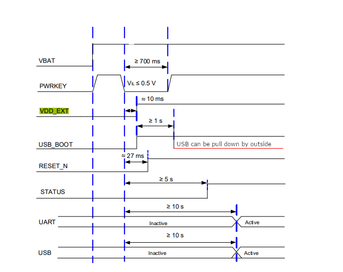
Typical Applications
Identifying Module Power Status: As described in the previous chapters, when the powerkey is triggered, the PMIC powers up the CPU and changes the module's power status, and VDD_EXT is pulled high simultaneously. Therefore, the pin level of VDD_EXT can serve as an indicator of the overall module's power status.
Used as a Constant Power Source or Pull-Up During Module Boot-up: Since VDD_EXT remains high during boot-up and has a certain output capability, it can be used as a constant pull-up or power source.
Due to the fact that VDD_EXT is generally powered by an LDO and may not have high driving capability, please make sure it meets the current consumption requirements of the device when used as a power source.
RTC Alarm
Overview of RTC Alarm
RTC (Real-Time Clock) is a unit on the PMIC and is usually driven by an LDO that can maintain power even when the module is shut down. Its core component is a set of counters that count using a 32K clock source and store real-time data in registers. The CPU can access these registers to obtain the time. When an RTC alarm expires, it can generate an interrupt, and most models can wake up the module.
Alarm Principle and Typical Applications
Alarm Principle
In addition to the registers that store real-time data, the RTC unit also has a set of readable and writable registers known as alarm registers. (Some module has multiple sets of readable and writable registers).The CPU can operate these registers to store a specific time as the alarm time.
When the RTC unit updates the time, it compares the real-time value with the alarm value set in the alarm registers. Once the real-time value matches the alarm value, it triggers an RTC alarm timeout interrupt. When the CPU is in shutdown state, this interrupt gives command to the PMIC to trigger CPU startup. When the CPU is in an active state, it can trigger a CPU interrupt (similar to a hardware timer).
Example code of the shutdown alarm:
import utime
from machine import RTC
from misc import Power

def Business_code_example(run_time):
    i = 0
    for i in range(run_time):
        print("Business app running")
    	#Business code here
        utime.sleep(1)

    return

def rtc_alarm_set(alarm_time):
    rtc = RTC()
    tm_rtc_tuple = rtc.datetime()
    tm_rtc_second = utime.mktime((tm_rtc_tuple[0], tm_rtc_tuple[1], tm_rtc_tuple[2], tm_rtc_tuple[4], tm_rtc_tuple[5], tm_rtc_tuple[6], 0, 0))

    alarm_second = tm_rtc_second + alarm_time #Set RTC alarm to the current time + alarm_time. Then the module restart after the alarm_time second(s)
    alarm_tuple = utime.localtime(alarm_second)

    rtc.set_alarm([alarm_tuple[0], alarm_tuple[1], alarm_tuple[2], alarm_tuple[6], alarm_tuple[3], alarm_tuple[4], alarm_tuple[5], 0])
    rtc.enable_alarm(1)

    utime.sleep(1)#For some modules, setting the RTC alarm is asynchronous and requires a certain delay to ensure that the underlying RTC information can be written."
    return

if __name__ == '__main__':
    alarm_time = 600 #RTC alarm triggers after 10 minutes
    Business_code_example(10)#Execute the business code

    rtc_alarm_set(alarm_time)#Set the alarm
    Power.powerDown()#Shut down the module after setting the alarm. The module will be awakened if the RTC alarm times out
Click here to download the complete code in GitHub.
Notes:
The RTC alarm and PSM T3412 on BG95 series module share the same alarm register and cannot coexist.
In terms of timing accuracy, the BG95 series module requires dedicated calibration and adjustment."
ADC
ADC Overview
Analog-to-Digital Converter, commonly referred to as ADC, typically refers to an electronic component that converts analog signals into digital signals. Conventional analog-to-digital converters transform an input voltage signal into an output digital signal.
ADC Principle
The basic principle of ADC is to sample the input analog signal at specified time intervals and compare it with a set of standard digital signals. The digital signal gradually converges, matching the two signals until they are equal. The converter then displays a binary number representing this signal.
Most PMICs in cellular modules have multiple ADC channels. Typically, one channel is fixed to sample VBAT, monitoring whether the VBAT voltage is within the legal range. Several other channels are open for external connections, allowing users to connect devices for sampling, and then read the values of these ADCs in the application layer.
Typical Applications
Monitoring Module VBAT Voltage
- Usage: Get Battery Voltage
- This ADC channel is fixed to monitor the VBAT voltage of the module. When powering the module using a battery, this interface can be used to manage the battery.
Aside from voltage measurement, when this ADC channel detects that the VBAT voltage is too high or too low, it triggers overvoltage/undervoltage interrupts on the PMIC. In this case, to protect the module hardware, the PMIC will actively change the power state, instructing the module to shut down.
ADC Usage
- Usage: ADC - Voltage Collection
- Connect a device that outputs an analog signal to an ADC channel, allowing you to read the voltage value that the device outputs. In this scenario, you can use the device's voltage value to calculate sensor data in the application.
Different PMICs have varying detection ranges for matching ADCs, which is determined based on the hardware design manual. If the output range of an analog device does not match the detected range of the ADC, voltage division may need to be designed in the hardware to match the output voltage with the ADC's effective range. In the application layer, the detected voltage can then be used to calculate the actual output value of the analog device.
Thermal Mitigation
Thermal Mitigation Overview
In the analog circuit of PMIC, there is often a temperature sensor. When the temperature is too high, integrated circuits may experience the risks of performance degradation, reduced frequency response, increased background noise, and even circuit meltdown. When the PMIC detects that the module is experiencing high temperature, it will proactively change the power state by forcing the module to shut down, thus protecting the hardware.
Thermal Mitigation Principle
The temperature sensor is an analog device whose output voltage changes with temperature. The PMIC collects its output voltage with the ADC, calculates the module's temperature, and regularly polls the temperature sensor's value. When this value exceeds the safe operating temperature of the module, the PMIC immediately changes the voltage state by forcing the module to shut down, thus protecting the hardware.
Typical Applications
High-temperature protection is typically implemented as built-in logic within the PMIC. From detection to actual protective actions, the entire process is managed by the PMIC. The safe operating temperature range is usually predetermined by the manufacturer, so the application layer typically does not need to be concerned about this aspect.
Other Features
Watchdog:
The watchdog, often referred to as a watchdog timer, is a timer circuit that typically has an input called "kicking the dog" or "servicing the dog", and an output that can control a CPU reset. When the CPU is working normally, it periodically sends a signal to reset the watchdog timer, preventing it from timing out. If the watchdog timer is not reset within a specified time (usually due to a program malfunction), it will trigger a reset signal to the CPU, causing it to restart. The watchdog's purpose is to prevent the program from entering an infinite loop or malfunctioning.
Codec:
In the hardware layer, an audio codec typically refers to a device that encodes analog audio into digital audio and decodes digital audio into analog audio. In other words, it includes both an Analog-to-Digital Converter (ADC) and a Digital-to-Analog Converter (DAC) running on the same clock. Some PMICs integrate audio codec into the analog circuitry, simplifying the module's hardware.
Device Charging:
The charging management unit is a relatively independent unit within the PMIC, including charging circuits, battery sensors, charging status indicator driver circuits, and more.
Charging management is a relatively independent function with its own hardware unit and control logic. This aspect will be further detailed in the following section.
Device Charging
Overview of Charging Solution
The charging solution for communication modules is generally implemented through the charging management unit of the PMIC. Some modules (EC200U, EG915U and EG912U series modules) can intervene in charging control through software while the module is powered on.
Principle of PMIC Charging Management Unit
The implementation form of the PMIC charging management unit is generally a linear charger. It starts working as long as the VBUS voltage is within the legal range.
Typical Architecture and Hardware Connection of Charging Management Unit:

The sensors of the charging unit generally include at least two ADCs, one monitoring the VBAT voltage and the other monitoring the battery internal resistance (actually monitoring the battery temperature through the change in internal resistance).
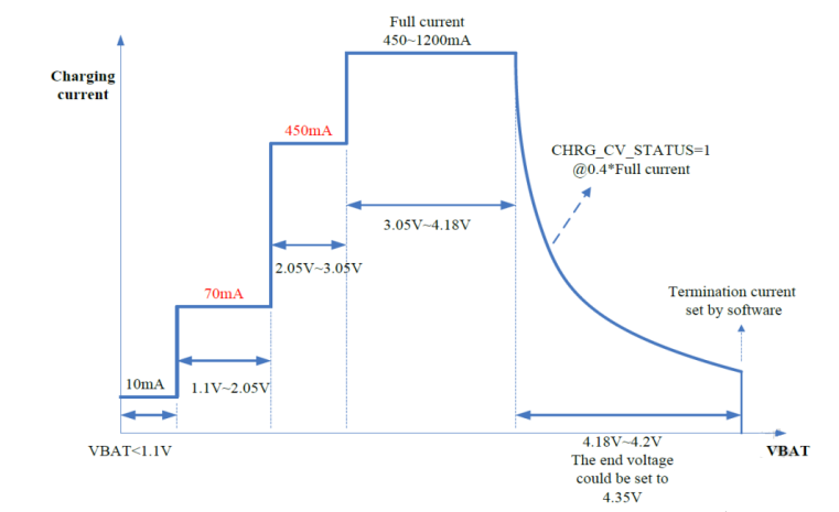
Charging Stage Control
Based on the VBUS voltage, the PMIC controls the charging management unit to enter different charging management stages. The typical divisions are as follows (different modules may have different names, but the principles are similar):
Trickle mode/activation mode: When the battery voltage is below a certain threshold, the battery management system prohibits charging the battery. At this time, a small current is needed to activate the battery to restore it to a chargeable state.
Pre-charging mode/low current mode: When the battery voltage is low, if full-power charging is performed, it may cause safety hazards such as high temperature and overvoltage to the battery due to the chemical characteristics of the battery. Therefore, when the voltage is lower than the full current charging threshold, the charging management power supply will charge VBAT with a lower current and voltage.
Full current mode/fast charging mode: At this time, the battery has reached a voltage that can be safely fully charged. A large constant current is maintained to quickly charge the battery.
Constant voltage charging mode: The battery is close to full load. At this time, a constant voltage is maintained, and the charging current gradually decreases as the voltage difference between VBAT and the charging unit decreases until it reaches full charge and charging stops.
Recharge: After charging is completed, VBAT voltage is polled. If VBAT drops below the recharge trigger voltage, constant voltage charging is performed.
Typical Charging Current and Voltage Curve:
Software Control of Charging
It is possible to adjust the charging behavior through software, such as stopping/starting charging, controlling the duty cycle of the constant current input, or obtaining battery voltage and temperature (only supported by EC200U, EG915U and EG912U series modules).
Shutdown Charging Solution
Overview of Shutdown Charging Solution
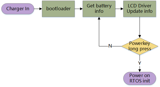
Shutdown charging refers to monitoring the charging status while the module is in a shutdown state when the power is plugged in for charging without turning on the module.
Implementation Principle
The charging unit itself contains an FSM that controls the charging stage. It can control the charging behavior when the CPU is not running. Therefore, the implementation is to monitor the charging status (such as VBAT voltage, battery temperature, etc., and may also need to be displayed ) without turning on the device.
At this time, when VBUS is pulled high by the power supply, the CPU is powered on through hardware linkage with the power key (if the PMIC supports triggering power-on by charger insertion, enable charger-triggered power-on instead of triggering the power key).
The logic of shutdown charging is implemented in the bootloader, mainly including polling battery status and LCD display, but it does not jump to the RTOS stage from the bootloader. If the powerkey is detected to be triggered again at this time, the normal boot-up process is entered.
Platform Support
Currently EC200U, EG915U and EG912U series modules have built-in charging management, while other modules can use external charging management chips.
Device Boot-up Process
Overview of Boot-up Process
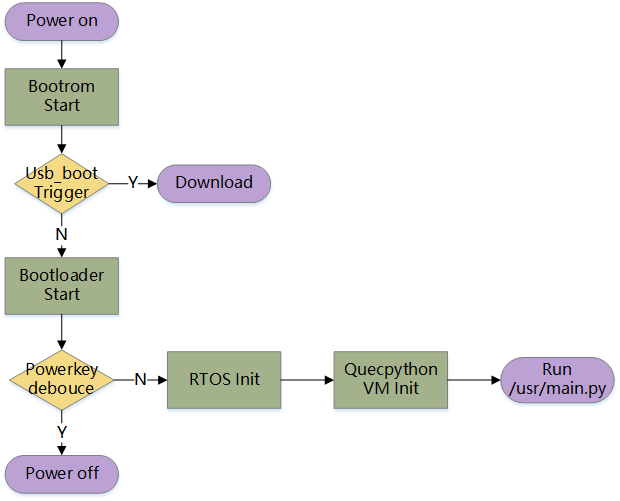
In general, the boot-up process can be divided into the following four parts:
- Bootrom: It runs immediately after power-on, usually stored in the ROM of the hardware.
- Bootloader: It initializes necessary peripherals and checks the code in the external storage. If the boot-up conditions are met, it jumps to the RTOS startup part.
- RTOS: The initialization of the RTOS is initialized and necessary tasks are started. At the end of this process, the QuecPython virtual machine thread is created.
- Initialization of QuecPython virtual machine: After initializing the communication interface, virtual file system, and network environment, it searches for and executes main.py in the usr partition.
The overall flowchart is as follows:
Bootrom
Bootrom is the code stored in the module hardware and is pointed to by the reset vector code. It is executed immediately when the module is powered on or reset. It generally includes functionalities such as forced download detection and basic initialization. Before the code running completes, it checks and boots the bootloader.
Bootloader
The bootloader is usually stored in the internal storage as the second-level boot. It completes some uncertain, relatively complex functionalities that are not convenient to be completed in the bootrom stage.
The functionalities of the bootloader may vary on different modules. The typical process is described below.
Basic BSP Peripheral Initialization
The bootloader needs to operate some peripherals, such as GPIO and UART. At this time, these peripherals are initialized.
Powerkey Debouncing
The bootloader generally cannot use ISR. Powerkey debouncing refers to polling the pin level of the powerkey within a threshold time. If the pin level is maintained for a time longer than the threshold, the boot process continues. Otherwise, the powerkey triggering is debounced, and operate the PMIC to shut down the module.
Determine Whether to Perform FOTA
Most modules' FOTA relies on the bootloader for redirection. Generally, a register is set as a flag before the last shutdown to indicate the need for FOTA. When the FOTA flag is detected, the bootloader does not jump to the RTOS system but jumps to the updater (generally a piece of code that can run independently, which writes the contents of the FOTA package to the specified flash address to complete firmware upgrade).
Deinitialize Relevant Peripherals and Jump to RTOS System Startup
Deinitialize the peripherals used in the bootloader and restore them to the state before the operation. Verify the integrity of the RTOS code area. If the verification passes, jump to the RTOS entry function. If it fails, it is generally considered that the image is damaged and jump to the download mode.
(EG912N and EG915N series modules support jumping to the LOGO stage, reading image resources from the file system, and initializing the LCD driver to display the boot logo. After the logo is displayed, it jumps to RTOS.)
RTOS Initialization
RTOS is the main program running on the module. Most communication modules initialize two sets of RTOS at this time to handle CP and AP tasks separately. The general initialization process is as follows:
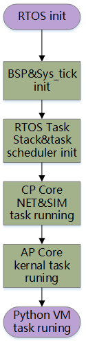
Initializing Clock and Peripherals to Prepare for RTOS Initialization
To obtain an accurate sys_tick, the CPU's tick is reinitialized (i.e., the tick is restored to 0). All peripherals are also set to the initial state after power-on. At this time, the BSP state should be aligned with the default level of the module.
RTOS Initialization
Initialize task stacks and task schedulers. When the task scheduler is initialized, the RTOS takes over the underlying layer, and the functions we call start running in the RTOS tasks.
CP Core Starts Network Search and SIM Card Tasks
The CP starts network search and SIM card tasks. The CP core provided by the manufacturer is generally not open source, so it will not be further described here.
AP Core Starts Necessary Internal Tasks
Start necessary internal tasks such as watchdog, FS, and protocol stack to complete the conditions for running the application.
Initializing QuecPython Virtual Machine
After the initialization of the RTOS internal environment is completed, start the App task. The App is typically a lower-priority task used to handle third-party business. Compared to the lower-level components, the QuecPython virtual machine functions as an App, it is initialized after the RTOS initialization is completed.
App Auto-Start during Module Boot-up
QuecPython Virtual Machine is the foundation for running Python. It initializes the interactive command line, file system, and network environment during boot-up, and by default executes a pyscript named main.py at the end.
The general process is as follows:
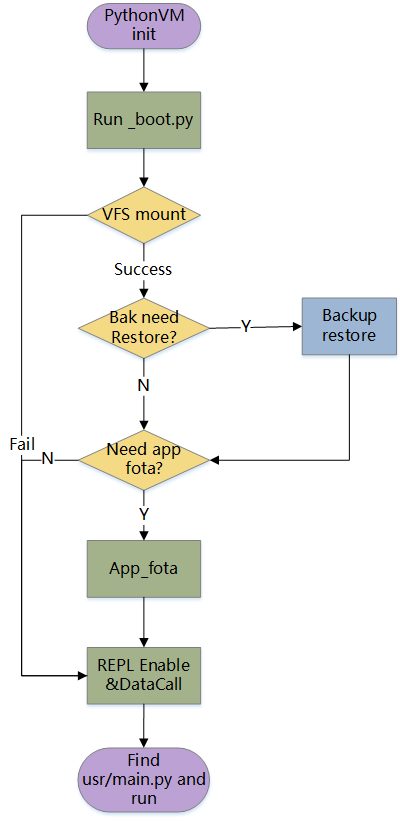
Initialization of Virtual Machine
The initialization of the virtual machine includes the initialization of the stack, GC and Python interpreter. After initialization, the pyscript can be executed. At this point, the next initialization step is performed in _boot.py.
Initialization of Virtual File System
To access the file system in Python, the physical module's file system needs to be mounted on the Python VFS. If the required littleFS file system is not initialized at the lower-level of the module, the physical file system needs to be initialized as well.
If the physical file system fails to initialize due to reasons such as unsuccessful initialization or SPI communication failure, the module will continue with the boot-UP process. However, the app_fota and backup and restore processes will be skipped. These two functions rely heavily on the file system and will fail if the file system is not initialized, rendering them meaningless.
Backup and Restore
When the backup and restore mechanism is enabled, if any files in the usr partition are missing or modified, they will be restored from the bak partition. If the backup and restore mechanism is not enabled or if there are no changes in the files in the usr partition, the backup and restore process will be skipped.
app_fota
The app_fota process checks whether app_fota is required. After the app_fota download is completed, a flag is written to the file system. If this flag is found in the file system, the app_fota upgrade process will be initiated. The downloaded content will be updated in the usr partition.
Initialization of the Interactive Command Line
Starting from this step, the processes is required. The REPL command line is launched, and if the interactive protection is enabled in system_config.json, the interactive protection feature will be enabled.
Automatic Dial-up
After the network environment is initialized, whether to perform automatic dial-up at boot-up is determined based on the configuration in system_config.json (enabled by default).
Execution of pyscript
After all the above steps are completed, the presence of main.py script in the usr file system is checked. If it exists, the script will be executed. Therefore, main.py is the fixed entry for App tasks.
Boot Logo Display
Scenario for Boot Logo
The boot logo needs to be displayed as quickly as possible since the virtual machine initialization and App loading take some time. Therefore, the logo needs to be displayed before the virtual machine starts.
Solution 1: Bootloader (For EG912N and EG915N Series Modules)
The code for the LCD and file system is introduced in the bootloader, and the LCD display is completed during the bootloader stage. This solution is suitable for scenarios with a longer boot time.
In the bootloader of EG912N and EG915Nseries modules, there is a code block named LOGO. Here, the littleFS file system and SPI LCD driver are adapted, which allows direct access to the data in the usr partition and drives the LCD to display the logo. Since the usr partition can be modified directly at the upper level, customers can easily replace the logo image.
Solution 2: RTOS (For EC200U Series Module)
After the RTOS initialization is completed but before the App starts, the screen is refreshed to display the logo. Then, the QuecPython virtual machine is initialized. This solution is suitable for scenarios with a faster boot time.
By mounting the lfs file system to the VFS at the lower-level of ECX00U series modules before the virtual machine starts, the file system can be accessed and the LCD can be driven to display the logo before the virtual machine initialization. Similarly, the logo image is stored in the usr partition, and customers can modify it directly at the Python layer.
Insert link to logo sample code provided by BSP colleagues here
Customizing Display
In both of the above solutions, the content to be displayed is stored in the usr partition of the file system. You can modify the logo content in the usr partition at the Python layer.
USB_BOOT
Overview of USB_BOOT
USB_BOOT is a fixed IO pin on the module. During the bootrom stage, if this pin is at a specific pin level, the module will directly enter the forced download/emergency download mode. After booting, it can be used as a normal IO pin.
Implementation Principle of Forced Download
Even if the module firmware is damaged or not programmed, USB_BOOT can still be triggered normally. The pin number, trigger level, and download mode redirection are all sotred and fixed in the ROM of the hardware. The code entry of this ROM is the CPU reset vector, so even if the code in the erasable storage medium is damaged, it does not affect the behavior of USB_BOOT here.
Usage
Scenario: Initial programming, unbricking, scenarios where it is not convenient to enter download mode with software control
Usage: Short the usb_boot pin to ground, and then power on the module. At this time, USB will not enumerate multiple ports, and only one download port will be visible to the host.
Possible download port names:
Quectel Download Port (EG912N and EG915N series modules)
Quectel QDLoader 9008 (BG95 series modules)
SPRD U2S Port (EC200U and EG91xU series modules)
Start flashing the firmware on the host as follows:
QPYCom: After loading the firmware, select the corresponding download port for the module based on the model, and then click "Firmware Download" to start the flashing process.
QFlash: After loading the firmware, select the corresponding download port for the module based on the model, and then click "Start" to start the flashing process.
USB_BOOT Boot Time Sequence Diagram:
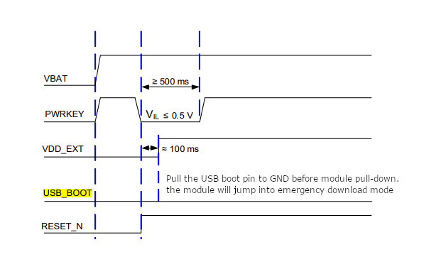
Note: When downloading is not expected, make sure to protect the pin level before the end of the boot process to prevent the module from detecting the pin trigger and entering download mode.