Overview
Sound is constantly present in our lives. Humans can hear sound through their ears and produce sound through their mouths, such as singing and reading. Similarly, computers can record sound through a microphone and play sound through a speaker, such as music playback or text-to-speech conversion.
The processing of audio signals by computers involves various audio-related techniques, such as audio sampling, encoding, decoding, text-to-speech conversion, and analog signal output. This article will focus on the principles and applications of audio technologies supported by QuecPython.
Audio Principles
DAC Principle
DAC (Digital-Analog Converter) converts digital signals into analog signals.
Audio DAC is a circuit that converts digital audio signals into analog audio signals. Its working principle generally consists of three steps: decoding, filtering, and amplification.
- Decoding: The digital audio signal is decoded into the sampling values of the analog signal according to certain rules. This process usually uses a multibit quantization high-order sigma-delta modulator structure.
- Filtering: The decoded analog signal is passed through a low-pass filter to remove high-frequency noise and jitter, resulting in a smooth analog signal. The filter has two types of roll-off characteristics: gentle roll-off and steep roll-off.
- Amplification: The filtered analog signal is amplified by a headphone amplifier to increase the signal power and driving capability, enabling it to drive headphones or speakers to produce sound.
The performance indicators of audio DAC mainly include:
- Bit Depth: It represents the number of bits of the digital audio signal before decoding, which determines the decoding accuracy and dynamic range.
- Sampling Rate: It represents how many times the decoding is performed per second, which determines the bandwidth of the signal.
- Signal-to-Noise Ratio: It represents the ratio of the effective signal to the noise in the analog audio signal, reflecting the quality of the signal.
- Total Harmonic Distortion: It represents the ratio of harmonic distortion to the effective signal in the analog audio signal, reflecting the linearity of the signal.
The selection of audio DAC should be based on specific application scenarios and requirements. Generally, high-end audio devices require high bit depth, high sampling rate, high signal-to-noise ratio, and low distortion audio DACs, while low-end audio devices can use low bit depth, low sampling rate, low signal-to-noise ratio, and high distortion audio DACs.
ADC Principle
ADC (Analog-Digital Converter) converts analog signals into digital signals.
Its working principle generally consists of four steps: sampling, holding, quantization, and encoding.
- Sampling: The input analog signal is discretized at a certain frequency to obtain a series of sampled values.
- Holding: The sampled values are temporarily stored on a capacitor for subsequent quantization and encoding.
- Quantization: The sampled values are divided into several levels according to certain rules, and each level is assigned a value, which is the quantization value.
- Encoding: The quantization values are represented by binary numbers to obtain digital signals.
The performance indicators of audio ADC mainly include:
- Bit Depth: It represents the number of bits of the digital signal after encoding, which determines the quantization accuracy and dynamic range.
- Sampling Rate: It represents how many times the sampling is performed per second, which determines the bandwidth of the signal.
- Signal-to-Noise Ratio: It represents the ratio of the effective signal to the noise in the digital signal, reflecting the quality of the signal.
- Total Harmonic Distortion: It represents the ratio of harmonic distortion to the effective signal in the digital signal, reflecting the linearity of the signal.
The selection of audio ADC should be based on specific application scenarios and requirements. Generally, high-end audio devices require high bit depth, high sampling rate, high signal-to-noise ratio, and low distortion audio ADCs, while low-end audio devices can use low bit depth, low sampling rate, low signal-to-noise ratio, and high distortion audio ADCs.
Common Digital Audio Interfaces
The purpose of digital audio interfaces is to transfer digital audio signals between different devices, such as DACs, ADCs, DSPs, audio processors and audio players. Digital audio interfaces can improve the anti-interference ability of audio signals, reduce signal loss and noise, and improve audio quality and efficiency. Digital audio interfaces can also support multi-channel and high sampling rate audio signals to meet different application requirements. The following are some common digital audio interfaces:
- I2S Interface: Short for Inter-IC Sound Interface. It is a serial audio interface used to connect digital audio devices such as DACs, ADCs and DSPs. It uses three lines to transmit data: BCLK, LRCK and SD. BCLK provides the data sampling rate, LRCK distinguishes between left and right channels, and SD transmits audio data. The I2S interface can support data widths of up to 32 bits and sampling rates of up to 192 kHz.
- PCM/TDM Interface: Short for Pulse Code Modulation/Time Division Multiplexing. It is a serial audio interface similar to I2S but supports multiplexing of multiple audio signals. It also uses three lines to transmit data: BCLK, FS and SD. BCLK provides the data sampling rate, FS distinguishes between different audio signals, and SD transmits audio data. The PCM/TDM interface can support up to 16 audio signals and sampling rates of up to 768 kHz.
Currently, the QuecPython modules support the PCM interface, which can be used for external codec. The pin definitions are as follows:
- PCM
| Pin Name | I/O | Description |
|---|---|---|
| PCM_CLK | DO | PCM clock |
| PCM_SYNC | DO | PCM frame synchronization |
| PCM_DIN | DI | PCM data input |
| PCM_DOUT | DO | PCM data output |
The number of PCM channels supported by different modules is as follows:
| Platform | I2S | PCM |
|---|---|---|
| EG912U-GL | 0 | 1 |
| EG915U Series | 0 | 1 |
| EC200U Series | 0 | 1 |
| EC200A Series | 0 | 1 |
| BG95 Series | 0 | 1 |
| BG600L-M3 | 0 | 1 |
| EG912N-EN | 0 | 1 |
| EG915N Series | 0 | 1 |
Cellular Module Hardware Framework
Built-in Codec
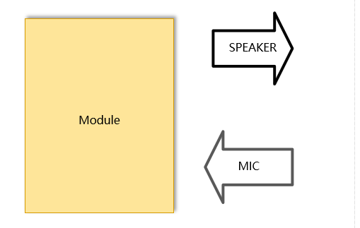
Codec (audio codec chip) is used for digitalizing and restoring audio signals. Audio codecs generally consist of two parts: ADC (analog-to-digital converter) and DAC (digital-to-analog converter). ADC is responsible for converting analog signals (such as microphone, line input, etc.) into digital signals (such as PCM, etc.), and DAC is responsible for converting digital signals (such as I2S, SPDIF, etc.) into analog signals (such as headphones, speakers, etc.). Some modules have a build-in codec to input and output audio analog signals directly, as shown in the following diagram:
External Codec
When the module does not have a built-in codec or when two codecs need to be used, an external codec can be connected via the PCM or I2S interface. In this case, the external analog input and output signals need to be connected to the codec, as shown in the following diagram:

External DAC
An audio DAC is an audio digital-to-analog converter, which is a device that converts digital signals into analog signals. It can convert audio data stored in digital media such as CDs, DVDs, MP3s, etc. into analog signals that can be output through speakers or headphones, allowing people to hear sound. The module can connect an external DAC via the PCM or I2S interface, as shown in the following diagram:

PWM Audio
PWM audio is a method of playing and processing audio using PWM (Pulse Width Modulation) signals, without the need of an external audio DAC (Digital-to-Analog Converter) chip. It is suitable for applications that do not require high audio quality but are cost-sensitive.
The main principle of PWM audio is as follows:
- PWM signal is a periodic square wave signal, and its duty cycle (the ratio of high-level time to one period) can be adjusted to change its average voltage value.
- Audio signal is an analog signal, and its amplitude and frequency can express the characteristics of sound such as loudness, pitch, and timbre.
- By sampling and quantizing the audio signal, a series of digital data representing the amplitude values of the sound at different time points can be obtained.
- By converting the digital data into corresponding PWM duty cycles, the PWM signal can be used to simulate the waveform changes of the audio signal.
- By outputting the PWM signal to devices such as speakers or headphones, sound can be reproduced.
PA Management
The role of the PA (Power Amplifier) audio power amplifier is to amplify weak signals from the audio source or preamplifier and drive the speaker to produce sound. The audio analog signals output by the module or codec are not strong enough and require control and optimization from the audio power amplifier (PA) to improve the quality and efficiency of audio output and protect the audio devices from damage. When the module outputs audio to the outside, such as playing audio files or using TTS, the PA needs to be turned on. When the module is in recording mode, the PA needs to be turned off to reduce power consumption and avoid noise being amplified by the PA.
Common Audio Applications
Audio Playback
Audio playback refers to the process of using an audio codec to convert audio files or audio streams into analog signals and play them through output channels such as earpieces, headphones, and speakers.
- To perform audio playback, an audio object needs to be created, specifying the output channel. For example,
aud = audio.Audio(0)means using the earpieces for output. - Audio playback can be done through the
aud.play(priority, breakin, filename)method, specifying the playback priority, interrupt mode, and file name. It supports playing files in mp3, amr, and wav formats. - The
aud.playStream(format, buf)method can be used to play audio stream, specifying the audio stream format and content. It supports playing audio streams in mp3, amr, and wav formats.
For more interfaces and detailed usage of audio playback, please refer to audio - Audio Playback.
Voice Call
Voice call refers to the process of converting voice signals into digital signals using a voice codec, transmitting them over the network to the other party, and then restoring them to voice signals using the other party's voice codec.
For more interfaces and detailed usage of voice call, please refer to voiceCall - Voice Call.
Recording
External sound is converted into electrical signals through the microphone input device, and then converted into digital signals through the codec and transmitted to the module. The module converts the digital signals into audio files of different formats (such as AMR and WAV) and stores them into flash.
The principle of recording is to convert sound signals into electrical signals or digital signals, and then store them on a medium for playback or processing.
- To perform recording, a record object needs to be created, specifying the input channel. For example,
record = audio.Record(0)means using the earpieces for input. - The
record.start(file_name, seconds)method can be used to start recording, specifying the recording file name and duration.
For more interfaces and detailed usage of recording, please refer to Record - Audio Record.
Audio Parameter Calibration
Overview
The audio calibration tool can adjust the input gain (including analog gain and ADC gain), output gain (including analog gain, DAC gain, and algorithm gain), and sidetone gain of the built-in codec. The validation modes include real-time mode and non-real-time mode, which can be controlled via APIs. In the non-real-time mode, the adjusted parameters will take effect in the next playback/call. The tool can be adapted to various application scenarios and various input/output channels. After adjusting the audio parameters with the audio tool, they can be directly fixed in the NV file as the default audio parameters.
Platform Support and Tool Applicability
ASR Platform
Currently, the ASR platform can calibrate audio parameters through the CAT-Audio tool in the CATStudio software. The main functionalities include:
Audio Path Calibration: It allows setting the gain at different volume levels.
CAT-Audio's audio path includes the ability to modify audio_gain.nvm and send AT*NVMFLUSH=1 commands. After modifying all the gains, to save the changes to flash, right-click on "Profiles" and select one of the three options:
- "Save Gain to NVM": Saves the modifications to NVM, which takes effect immediately and the configuration is saved even after restarting.
- "Create Default NVMs": Restores the original NVM if the parameters are not saved to NVM.
- "Reload NVM files": Retrieves the original NVM from the CP.
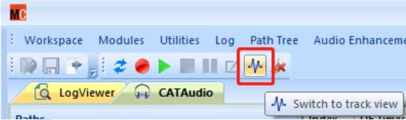
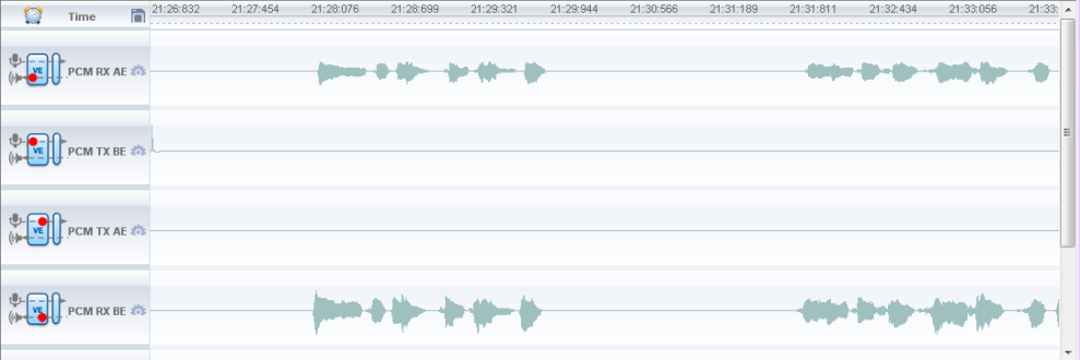
Call Recording and Playback: Click the icon of "track view"to display the track view interface.
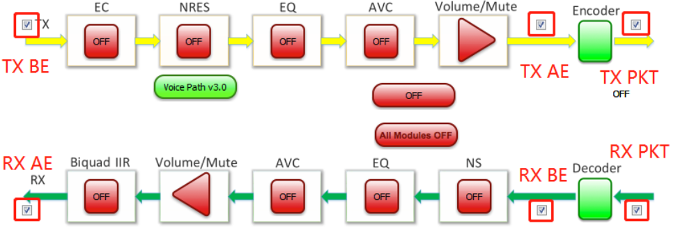
In the VE topology, select the link where the recording is needed.
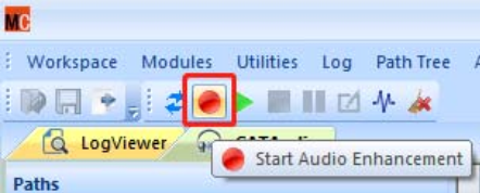
Click the red circular button to start real-time recording, and the real-time waveform can be seen in the track view.
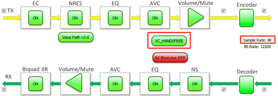
Speech Enhancement Audio Calibration: The speech enhancement topology provides control over all speech enhancement modules. It supports enabling or disabling each module and setting parameters within the modules.
Unisoc Platform
The Unisoc platform uses the AudioCalibrator software for audio parameter calibration. The main codec parameters include:
Built-in Codec Input Gain (atctst_aud_codec_get_ingain):
The input gain refers to the microphone gain in call mode, which cannot be adjusted in music playback mode. The analog gain and adc gain can be modified as shown in the following figure. The analog gain range varies for different channels, while the adc gain range remains the same. The value should not be too large, or else input distortion may occur.

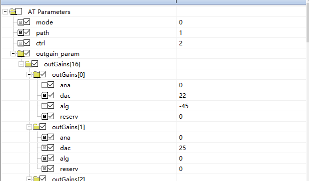
Built-in Codec Output Gain (atctst_aud_codec_get_outgain):
The output gain can be adjusted in both call mode and music playback mode. The output gain is related to the volume level and currently supports 0–11 levels, corresponding to outGains[0] to outGains[11] in the gain list. To readjust the volume gain, the corresponding dac, ana, and alg gains can be adjusted. Setting alg to the minimum achieves mute. It is not recommended to set the dac value higher than 63 because it may cause distortion. Users can set different gain combinations based on the application scenario. It is suggested to keep ana and alg value unchanged and adjust the dac gain.
Sidetone Gain (atctst_aud_codec_get_sidetonegain):
The sidetone gain is used in call scenarios. The sidetone is disabled by default, but it can be adjusted here if needed.