
Memory Device
This document aims to introduce the types, usage, and common issues of QuecPython storage devices, and provide guidance for using QuecPython storage devices.
Overview
QuecPython device storage system consists of internal storage and external storage. The internal storage system is generally NAND flash or NOR flash, while the external storage is to expand storage space through interfaces such as SPI and SDIO, which can be flash, SD card, EMMC, etc. There are two ways to use the storages. One is to mount a file system to store data and parameters. Common file systems include littleFS, FATFS, EFS, SFFS file systems, etc. The other is to access the raw partition directly without mounting a file system to store code images, configuration parameters, GUI fonts, etc. NOR flash can directly run code, while NAND flash cannot run the code directly.
Internal Storage
Overview
The internal storage is the necessary storage space for the normal operation of the device. It is used to store images and data. It is generally divided into multiple partitions according to their functions, and each partition is relatively independent. Whether to mount a file system or use it as a raw partition depends on the functional requirements.
Partition Table
Modules with different hardware may have different partition configurations (different partition tables). Generally, they can be divided into the following parts:
a) Image area: the area where the low-level and the application layer processing programs and other images are stored.
b) Factory parameter area: the area where RF parameters, module configurations, etc. are stored. There will also be a backup area, which will be used to restore data in case of abnormal damage, ensuring the normal operation of the module.
c) User parameter area: the file system partition used to store script files and user parameters.
Partition Distribution on Different Modules
EG91xN Series Module
Taking the EG915N series module as an example:
| Partition | Description |
|---|---|
| bootloader | Stores the bootloader images |
| ptable | Stores flash partition information |
| fwcerts | Stores firmware certificates |
| rd | Stores trusted data |
| apn | Stores APN images |
| cp | Stores kernel images |
| dsp | Stores network protocol stack images |
| rfbin | Stores RF driver images |
| logo | Stores boot logo display images |
| reserved | Reserved |
| fota_pkg | Stores FOTA delta package |
| customer_app | Stores App images (implemented by QuecPython program) |
| customer_fs | User file system (corresponding to the "usr" disk) |
| customer_backup_fs | User file backup system (corresponding to the "bak" disk ) |
| backup_restore_info | Stores backup and restore information |
| fota_param | Stores FOTA upgrade parameters |
| updater | Stores FOTA upgrade program images |
| erase_rd | Stores flash erase information record |
| nvm | System parameter file system |
| secdat | Stores user non-volatile data |
| quec_cfg | Quectel custom parameter partition |
| factory_a | Stores basic configuration and RF factory parameters |
| factory_b | Stores backup basic configuration and RF factory parameters |
EC200U&EG91xU Series Module
Taking the EG915U series module as an example:
| Partition | Description |
|---|---|
| bootloader | Stores the bootloader images |
| ap | Stores kernel-side AP image (processed by the application) |
| customer_app | Stores App images (implemented by QuecPython program) |
| fs | Low-level file system partition (stores FOTA differential packages, etc.) |
| secdat | Stores user non-volatile data |
| fs_config | Stores user file system configuration information (used to dynamically adjust the size of "usr" and "bak") |
| customer_fs | User file system (corresponding to the "usr" disk) |
| customer_backup_fs | User file backup system (corresponding to the "bak" disk) |
| modem | Stores kernel-side CP images (processed by the network) |
| factory | Stores basic configurations, RF and other factory parameters |
EC200A Series and UC200A-GL Module
Taking the EC200A series module as an example:
| Partition | Description |
|---|---|
| NTIM | Stores partition table information |
| bootloader | Stores bootloader images |
| MRD | Stores reliable parameters of the low-level |
| MRD_backup | Stores reliable backup parameters of the low-level |
| logo | Stores boot logo display images |
| cp | Stores kernel images |
| customer_fs | User file system (corresponding to the "usr" disk) |
| customer_backup_fs | User file backup system (corresponding to the "bak" disk) |
| dsp | Stores network protocol stack images |
| rf | Stores RF information |
| fota_pkg | Stores FOTA upgrade backup information |
| PSM backup | Stores PSM backup information |
| FAT map | File system directory of the low-level |
| FAT sys | Low-level file system |
| customer_app | Stores App image (implemented by QuecPython program) |
| block erase record | Stores flash erasing record |
| updater | Stores FOTA upgrade program images |
| FBF | Stores tr69 parameters |
| fota_param | Stores FOTA upgrade parameters |
| QuecCfg | Stores important parameters of the low-level |
| PSM | Stores network protocol parameters of the low-level |
| VSIM profile | Reserved |
| VSIM profile backup | Reserved |
| factory_a | Stores basic configurations, RF and other factory parameters |
| factory_b | Stores backup information of basic configurations, RF and other factory parameters |
BG95&BG600L Series Module
Taking BG95-M3 as an example:
| Partition | Description |
|---|---|
| reserved | Reserved |
| bootloader | Stores bootloader images |
| mibib | Stores partition table information |
| qdsp_swap | Stores network processing swap data |
| efs2_factory | Backup area for efs2 |
| efs2apps_factory | Backup area for efs2apps |
| efs2 | CP (processed by the network) file system |
| qdsp_paging | Stores kernel CP related images (processed by the network) |
| qdsp | Stores kernel CP related images (processed by the network) |
| qdsp_tiny | Stores kernel CP related images (processed by the network) |
| tz | Stores Trustzone images |
| rpm | Stores RPM images |
| tz_devcfg | Stores Trustzone configuration images |
| ap | Stores kernel AP images (processed by the application) |
| adcb | Stores audio images |
| apdp | Stores application debugging images |
| loader_sti | Stores test images |
| multiimgoem | Stores multiimgoem images |
| multiimgqti | Stores multiimgqti images |
| scrub | Stores FOTA delta package |
| secdata | Stores security configurations |
| misc | Stores backup and restore result flags |
| customer_app | Stores App images (implemented by QuecPython program) |
| customer_backup_fs | User file backup system (corresponding to the bak disk) |
| efs2apps | AP (processed by the application) file system (including user file system usr) |
For the space resources provided to users by each platform, see Hardware Plaforms Supported by QuecPython.
Adjusting Partitions
As described earlier, the available space provided to users is divided into two partitions: the user file system partition (corresponding to the usr disk) and the user file backup system partition (corresponding to the bak disk) . If the default distribution of these two partitions does not meet the user's application requirements, you can use the QPYcom tool to adjust the partitions. Partition adjustment may be needed when a large number of files need to be stored, with some files not needing backup, such as log storage applications. In this case, the size of the user file backup system partition can be reduced and the size of the user file system partition can be increased to meet the requirements.
Supported Scenarios:
Currently, only the EG912N and EG915N series modules support partition adjustment. It only supports adjusting the size between the user file system partition and the user file backup system partition.
Procedure:
Taking the EG915U series module as an example:
- Click "Function Box" -> "Partition Management" -> "UNISOC"
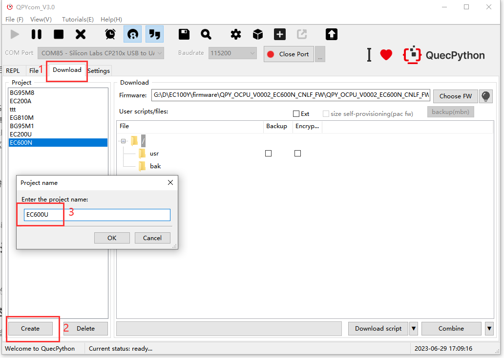
- Select the firmware file, such as QPY_OCPU_V0003_EG915U_EUAB_FW\QPY_OCPU_V0003_EG915U_EUAB_FW.pac, showing the sizes of the "usr" and "bak" partitions, as well as the total size of both partitions.

Drag the progress bar or enter in the text box to change the size of the usr partition, The size of the bak partition will be automatically updated to the new value.
Click the "Confirm" button to start generating firmware and wait for the new firmware to be generated..

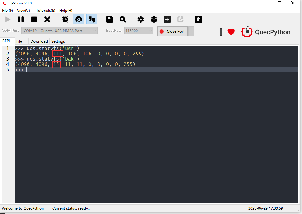
Flash the combined firmware and check the new partition size distribution:
Adding a Partition
Scenario:
After the firmware is released, users may need to add a new partition to the original partition table to meet application requirements, such as adding a GUI font library partition to store font files.
Supported Scenarios:
Currently, only the EG912N and EG915N series modules support adding partitions and only specific partitions such as the GUI font library partition (which needs to be used with GUI code in the low-level) can be added. The starting address and maximum size of the new partition are fixed by the QPYcom tool. For EG912N and EG915N series modules, the App images are copied to RAM and executed in RAM, so the starting address of the App can be changed. The reserved and customer_app partitions can spare the space to the new partition. ).
Procedure:
To be supplemented.
Matters Needing Attention
The minimum size of a file system partition cannot be less than 32 KB. The starting address and size of each partition need to be multiples of 4 KB. The QPYcom tool has already followed this rule when adjusting the partitions.
Flash Firmware to Internal Flash
Flashing Principle
The flashing function is designed differently on different modules, and the overall flashing mechanism is as follows:
a) Enter the download mode, which is generally achieved by configuring the level of specific pins or sending specific commands to restart the device. At this time, the program stored in the ROM is executed. Since the program is stored in the chip, both the storage space and the operating space are limited, so the logic is relatively simple.
b) In the download mode, initialize the UART or USB hardware communication feature, and then download the extended flashing program to the chip's RAM through UART or USB.
c) Hand over control and jump to the extended flashing program in RAM to perform further flashing features. The main purpose of this step is to download the entire firmware to the flash. Its functionalities include initializing the flash, partitioning, reading and writing flash, etc. The communication mechanism between the host and the device generally adopts the "command-response" mode. The host application sends a command, the module receives it and executes the corresponding command, and then sends the response back to the application. The interaction process mainly includes: connection, download start, download in progress, download complete. Both commands and data will undergo CRC verification to ensure the reliability of the data.
d) Flashing completed. Restart the device to run the flashed firmware.
When you actually use it, you can use the flash tool to load the firmware, put the device into download mode, and connect the device through a USB or UART cable to start flashing. For specific flashing operation details, see local upgrade guide.
Overview of Flashed Partition
When the firmware is flashing, different partition processing methods are used for different partitions. The overall strategy is to erase and write new content for the image partitions, user file system partition and user file backup system partition. and that the secure data area and the low-level parameter area are maintained and not erased.
Mass Production Firmware
The reason for generating mass production firmware is that the official firmware released by QuecPython only includes the programs of the platform layer and the QuecPython adaptation layer. Users need to use the QuecPython Modules API and write programs in Python to implement the complete functionality of the application. These Python programs need to be stored in the user file system partition and user file backup system partition in the form of files. During the debugging phase, flash the user files to the device's user file system partition through QPYcom download script function. However, during mass production, to improve efficiency, the debugged files need to be packaged into the QuecPython official firmware in advance, so that the QuecPython official firmware and user files can be flashed into the device together. The general steps are as follows. When the device leaves the factory, it has the default firmware that does not include QuecPython related features. Users need to flash the firmware officially released by QuecPython, and after developing and debugging the user application functions based on the QuecPython module, package the user's script files and QuecPython firmware into one firmware. This firmware is then flashed into all devices as the final mass production firmware. For details on generating the mass production firmware, see Combination of Firmware and Script.
Common Applications of Internal Storage
Program Image
Store the program image required for device operation, generally including the bootloader, kernel, and app.
File System
Mounting a specified partition as a file system to store data allows data to be managed in the form of files, including operations such as creation, reading, writing, and deletion. It is suitable for storing large amounts of data that are frequently modified and non-critical. For details on file system usage, see File System Application Note.
GUI Fonts
A specified partition is used to store the font content required for GUI display. This font content contains different font information and has a fixed structure. Therefore, the font file needs to be flashed into the specified partition of the device together when you flash the firmware. In this way, the GUI display program can directly access the font content through the flash related interface, which is faster than accessing through the file system and can improve the real-time performance of GUI display.
Raw Partition Operations
For example, use a specified partition to store user secure data so that the data can be saved after power-off. The data comes from the content generated by the user during the device operation in real-time. Therefore, this partition does not need to flash specific content to the specified partition in advance, and the partition is not erased during the flashing process. This method is suitable for storing small amounts of data that are not frequently modified and are critical. For usage details, please refer to SecureData - Secure Data Partition for API usage.
External Storage
Overview
The internal storage space of the module is mainly used to store code images and parameters, and the remaining space available to customers is limited. If additional storage space is required, an external storage device needs to be connected. For example, NOR flash, SD card, NAND flash, etc. The hardware communication interfaces include SDIO interface and SPI interface, and the currently supported methods are: SPI NOR flash, SDIO SD card, SDIO eMMC, and SPI SD card.
SPI NOR Flash Application
Principle Overview
This usage involves connecting a NOR flash storage chip outside the module through SPI hardware pins. After initializing the flash driver through the application program, read and write operations can be performed on it. You can choose the specific flash chip based on the specific space requirements. According to the number of SPI pins used for communication, it can be divided into 4-wire external flash and 6-wire external flash schemes. The 6-wire flash scheme has a higher communication speed than the 4-wire scheme, so it can directly run the program.
Application Scenarios
Program Image
The external flash is used to store the QuecPython program images, so that more features of the low-level can be opened to meet the diverse application scenario requirements. As mentioned above, this scheme must use the 6-wire SPI NOR flash. The program running with this scheme is the same as running the program placed in the internal storage. Currently, only specific models of the ECx00U&EG9xxU series modules support this feature. Please consult Quectel Technical Support for specific models.
File System
Similar to the internal storage, the specific partition of external flash can be mounted as a file system to store data. This allows data to be managed in the form of files, including operations such as creation, reading, writing, and deletion. It is suitable for storing large amounts of data that are frequently modified and non-critical. For details on using the external flash file system, please refer to File System Application Note.
GUI Fonts
Similar to the internal storage, the external flash can be used to store the font content required for GUI display. This font content contains different font information and has a fixed structure. Therefore, when you are flashing the firmware, the font file needs to be flashed into the specified partition of the device together. In this way, the GUI display program can directly access the font content through the flash interface, which is faster than the file system method and can improve the real-time performance of GUI display.
Supported QuecPython Modules
Currently only EG912N, EG915N , EC200U, EG912U and EG915U series modules support external SPI NOR flash.
Usage Details
Hardware Connection
The SPI NOR flash uses the SPI communication bus. It depends on hardware resource availability and user requirement to select the specific SPI pin.
For a 4-wire SPI NOR flash setup, please refer to the details of the SPI pin correspondence in SPI – Serial Peripheral Interface Bus Protocol. Since other peripherals like an LCD may also need to use SPI to communicate, it is essential for users to allocate hardware resources in advance and ensure that each device uses a different SPI channel to avoid conflicts with the NOR flash.
Currently only the EC200U and EG915U series modules support the 6-wire SPI NOR flash scheme. The pin usage is as follows:
| Purpose | Pin Function | EC200U Pin Number | EG915U Pin Number |
|---|---|---|---|
| SPI1 | SPI_FLASH_CS | 26 | 5 |
| SPI_FLASH_CLK | 27 | 4 | |
| SPI_FLASH_SIO0 | 24 | 6 | |
| SPI_FLASH_SIO1 | 25 | 7 | |
| SPI_FLASH_SIO2 | 13 | 1 | |
| SPI_FLASH_SIO3 | 135 | 20 | |
| SPI2 | SPI_FLASH_CS | 124 | 106 |
| SPI_FLASH_CLK | 125 | 116 | |
| SPI_FLASH_SIO0 | 123 | 105 | |
| SPI_FLASH_SIO1 | 122 | 16 | |
| SPI_FLASH_SIO2 | 121 | 108 | |
| SPI_FLASH_SIO3 | 119 | 92 |
As shown in the table, for EC200U and EG915U series modules, if the MIPI LCD function is not used and only the 6-wire SPI NOR flash is connected externally, any of the two SPI channels can be selected as the flash SPI communication interface. If both the external 6-wire SPI NOR flash and the MIPI LCD function need to be supported, the flash SPI communication interface must be selected as SPI2.
Adding Models
After selecting the NOR flash chip model, you need to check if the device firmware supports the flash model. You can use the QPYcom tool to load the firmware version and check the flash models currently supported by the firmware (QPYcom is under development) (to be supplemented).
If the flash model is not in the support list of the firmware, you need to add the flash model to the device. You can add the specified flash model when you use the the QPYcom tool to combine the firmware (QPYcom is under development).
Partition Adjustment
After the firmware is released, you need to add the external flash partitions to meet application requirements, such as adding a GUI font partition to store font files. Currently, only EG9xxN series modules support adding partitions, such as adding file system partition and GUI font partition, but should be used with GUI code of the low-level. The starting address and size of the new partition can be specified with the QPYcom tool. Similarly, users can also adjust the external flash partitions, such as adjusting the sizes of the file system partition and GUI font partition. Specific operations will be supplemented after the QPYcom tool supports them (to be supplemented).
Flashing
The flashing method for firmware with an external flash is the same as that for firmware with an internal flash. Please note that flashing with an external flash depends on the external flash chip, because successful communication with the external flash needs to be ensured. The SPI port information of the flashing tool needs to be specified when creating the firmware. Specific operations will be supplemented after the QPYcom tool supports them. If the download fails, please check if the flash chip is correctly soldered and if the SPI pin connections are correct.
Mass Production Firmware
The process of creating mass production firmware with external flash functionality is generally the same as that with internal flash. The difference is that the external flash needs to configured the flash model, specified SPI port, and partition allocation. Specific operations will be supplemented after the QPYcom tool supports them (to be supplemented).
Software Interface
For the file system partition scenario, the file system can be used after it is mounted. For the initialization of the external flash file system, refer to uos -Registering the Storage Device littleFS - SPI NOR FLASH.
Read/Write Speed
Because the external flash communicates with the CPU through the 4-wire SPI, the internal flash communicates with the CPU through the 6-wire SPI, and the internal flash has higher SPI clock frequency compared to the external flash, the reading and writing speed of the external flash is lower than that of the internal flash. The speed difference is about 4 to 8 times. Therefore, when you develop applications with the external flash, the impact of the speed bottleneck on the business needs to be considered, such as the GUI display function that requires high real-time requirement and involves the storage and access of images and font files. For such application scenarios, a caching mechanism can be used to reduce the impact by caching frequently accessed data in RAM and directly reading from RAM the next time if the same data is accessed. This mechanism is generally implemented by the firmware at the lower level, and users can configure the size and number of the cache.
SD Card Application
Overview
SD Card (Secure Digital Memory Card) is a type of storage card based on semiconductor flash technology. It can be divided into SD, mini-SD, and micro-SD based on appearance. According to the capacity of the SD card, it can be divided into three standards: SDSC (SD Standard Capacity) (capacity not exceeding 2 GB), SDHC (SD High Capacity) (capacity greater than 2 GB but not exceeding 32 GB), and SDXC (SD Extended Capacity) (capacity greater than 32 GB but not exceeding 2 TB). The SDIO interface or SPI interface can be chosen as the communication interface.
SDIO Interface
The SDIO interface uses the SDIO bus to communicate with the SD card. SDIO is a secure digital input and output interface, which is evolved from the SD memory card interface. The SDIO interface is compatible with the SD memory cards and can be connected to devices that support the SDIO interface. There are three modes of SDIO signals: "single-wire mode", "4-wire mode", and "SPI mode". Here we use the "4-wire mode".
SPI Interface
The SPI interface uses a generic SPI bus to communicate with the SD card, including initializing the SD card and performing read and write operations on the SD card.
Usage Details
Hardware Connection
Refer to the hardware design manual for the SD card interface-related chapters for the hardware pin connections of the SDIO interface. Refer to SPI – Serial Peripheral Interface Bus Protocol for hardware pin connections of the SPI interface in the detail introduction of SPI pin correspondence .
File System Type
The SD card function uses the FATFS file system, which supports FAT32 format compatible by Windows .
Software Interface
The SD card function can be used after file system is mountedg. Refer to Registering the Storage Device - SPI - SD Card for specific code examples. Refer to Registering the Storage Device - SDIO - SD Card for detailed usage of SDIO SD card interfaces.
Hot Plug
Currently, only SDIO SD cards support card insertion and removal detection, and specific code needs to be used in conjunction. Refer to Setting the Pin for SD Card Detection for specific code examples.
Read/Write Speed
Because 4 wires are used for data transmission in the SDIO interface and only one wire in SPI, the SDIO mode has a higher read/write speed than the SPI mode. The write speed of SDIO SD cards can reach 5 MB/s, and the write speed of SPI SD cards can reach 600 KB/s.
Application Scenarios
Common scenarios include storing audio files (playing audio files with streaming playback), storing historical positioning information, and storing logs.
Supported Modules
SDIO SD card function is only supported by the EC200U, EG912U and EG915U series modules. SPI SD card function is only supported by EG912U and EG915U series modules.
Common Issues
Mounting Failure
If the file system mounting fails, it means that the hardware communication is not successful. Check whether the SD card interface pins are connected correctly and firmly. Also, check if the SD card power supply voltage meets the SD card standards.
Formatting
If there are file system abnormalities or the file system space is full, you can use the formatting interface to format the SD card. Refer to Mounting the File System for specific interface examples.
Common Issues
NOR Flash Lifespan
The maximum erase/write times of NOR flash is about 100,000 times. Please avoid frequent erase/write operations during use. NOR flash has a simple interface, fewer data operations, and fewer bit swapping operations. Therefore, it has high reliability and is considered not to have bad blocks, so there is no need for bad block management.
NAND Flash Lifespan
The maximum erase/write times of NAND flash is about 1 million times. Please avoid frequent erase/write operations during use. The NAND flash interface and operations are relatively complex, and there are many bit swapping operations, so it has higher chances that issues occur, and bad blocks are inevitable. Therefore, bad block management is required, and the bad block management mechanism is implemented by the low-level code.
Differences between NOR Flash and NAND Flash
NOR flash can directly run programs, while NAND flash cannot. Due to the fact that all operations on NAND flash are performed in blocks and pages, when performing a large amount of data read/write operations on NAND flash memory, the speed is faster than that of NOR flash. The capacity of NOR flash is relatively small, generally around 1–16 MB. The capacity of NAND flash memory is larger, with a maximum capacity of up to 8 GB.