
Introduction to FCM360W te-b development board
Supported module list
Function list
Basic overview
QuecPython_FCM360W_TE-B development board is a Wi-Fi and Bluetooth development board launched by Quectel. Equipped with FCM360W module, it supports Wi-Fi 6 and Bluetooth 5.1 wireless connections, and provides large memory including 512 KB SRAM and 4MB flash memory.
The development board connection interface is two micro-usb interfaces, and provides a variety of interfaces, including UART, SPI, I2C, ADC, etc. The supporting antennas include external pin antennas, PCB antennas, etc.
Functional Description
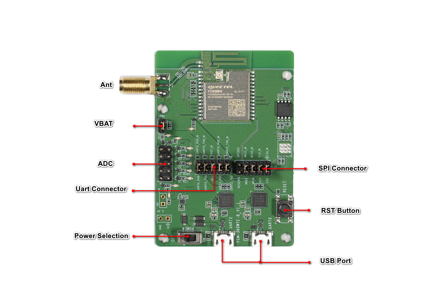
The main components and interface layout of the development board are shown in the figure below
Download
Development Board Resources
Development board interface
The main pin layout of the development board is shown in the table below
| Pin header | Name | Pin | Function |
|---|---|---|---|
| UART | UART0_RXD | 26 | UART0 receive |
| UART | UART0_TXD | 27 | UART0 send |
| UART | RST | 11 | Module reset |
| UART | UART2_RXD | 19 | UART2 receive |
| UART | UART2_TXD | 20 | UART2 send |
| UART | UART0_RXD_M | 26 | UART0 |
| UART | UART0_TXD_M | 27 | UART0 |
| UART | RST_M | 11 | Module reset |
| UART | UART2_RXD_M | 19 | UART2 |
| UART | UART2_TXD_M | 20 | UART2 |
| SPI | RESERVE | 17 | Reserved |
| SPI | MOSI | 29 | SPI Master Output Slave Input |
| SPI | MISO | 23 | SPI Master Input Slave Output |
| SPI | CLK | 22 | SPI Clock |
| SPI | CS0 | 21 | SPI Chip Select |
| SPI | GPIO25 | 16 | GPIO25 |
| SPI | MOSI_M | 29 | SPI Master Output Slave Input |
| SPI | MISO_M | 23 | SPI Master Input Slave Output |
| SPI | CLK_M | 22 | SPI Clock |
| SPI | CS0_M | 21 | SPI Chip Select |
- The pins with _M in the name are directly connected to the module end
Tips
For more information about the development board, please visit https://python.quectel.com/en/resource-download?cid=252
Development board configuration
The peripheral resource pin allocation table is as follows:
| Serial number | Name | Model | Supported | Interface type |
|---|---|---|---|---|
| 1 | USB to serial port | CP2102 | Yes | UART |
| 2 | Button | - | Yes | GPIO |
| 2 | ANT | - | Yes | - |
Getting started
First, you need a computer running Windows 10 or above operating system
- Step1: Burn firmware to the development board
First, use micro Use the USB data cable to connect the UART0 interface on the development board to the USB port of the computer to complete the power supply. Switch the POWER switch of the development board to the ON state, and then use the QPYcom tool to burn the firmware
- Step2: Development board connection
After completing the above firmware burning steps, switch the data cable connection from UART0 port to UART2 port, and use the serial port tool to connect to the serial port. The serial port tool uses QCOM ,You need to check the RTS check box of the tool first, and then open the serial port
- Step3: Development board interaction
After completing the above connection steps, press the onboard RESET button to see the module startup information. The serial port is the REPL port of QuecPython, and repl interaction can be performed normally through the serial port tool