
Introduction to EG91X Evaluation Board
Supported Module List#
Feature List#
Basic Overview#
The QuecPython_EG91X series C1-P02 evaluation board is a compact and portable "pocket-sized" board designed specifically for QuecPython.
The main equipped modules are the EG915U series LTE Cat 1 wireless communication modules, which are also compatible with Quectel's EG91 series, EG95 series, BG95 series, and BG96 modules in terms of packaging. This allows for seamless switching between 2G and 4G networks to meet the application requirements of different industries.
The evaluation board has a built-in Type-C interface, making it convenient for development. Developers only need a USB Type-C cable to easily use the evaluation board.
Additionally, the evaluation board is compatible with the expansion board of Raspberry Pi Zero, which can be directly used on the evaluation board.
Evaluation Board Resources#
Function Description#
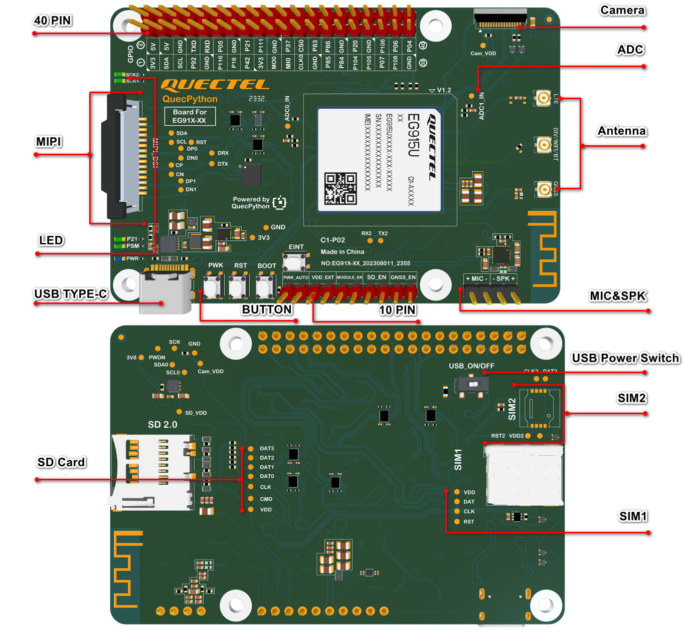
The main component and interface placement of the evaluation board is shown in the following figure:
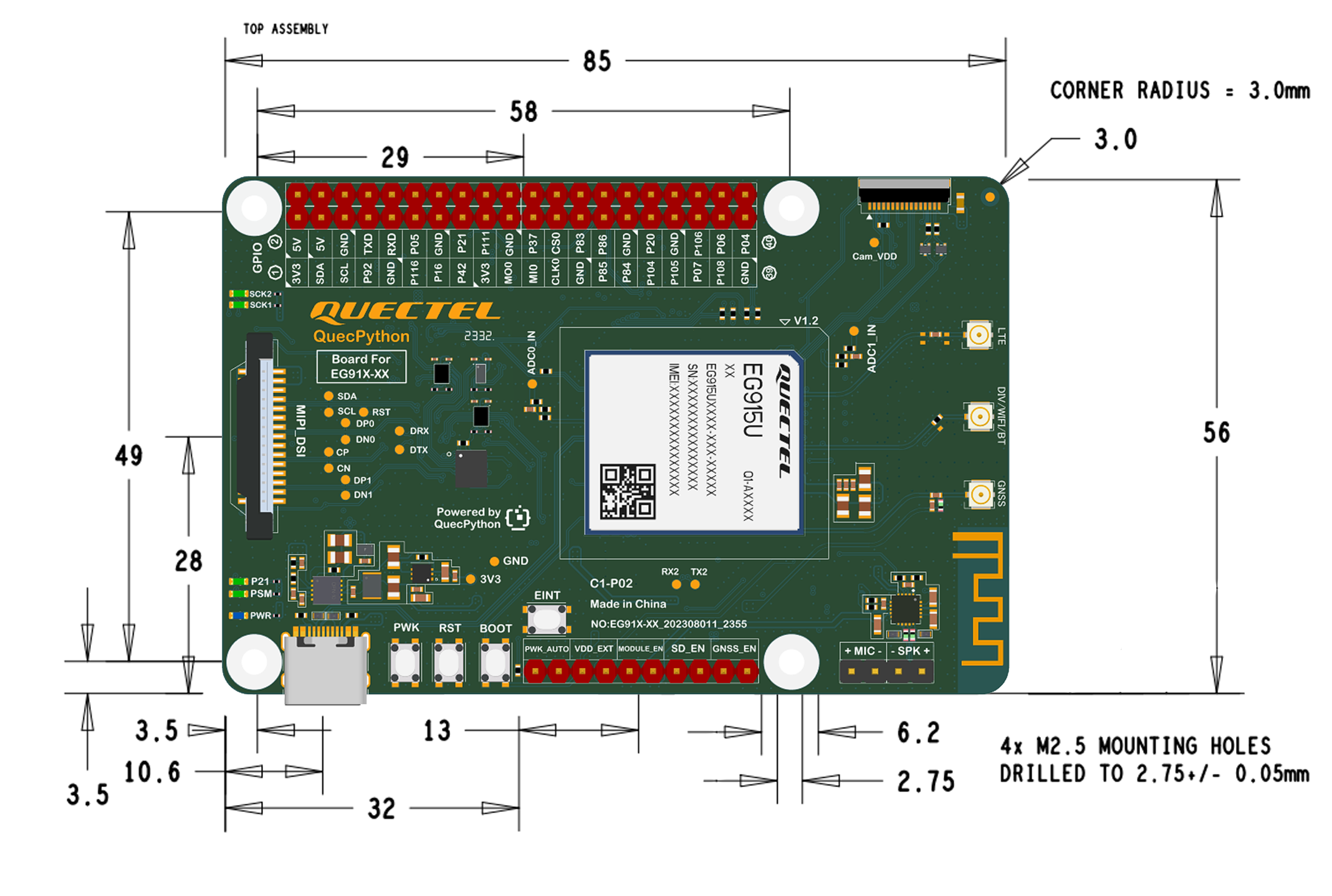
Evaluation board dimensions:
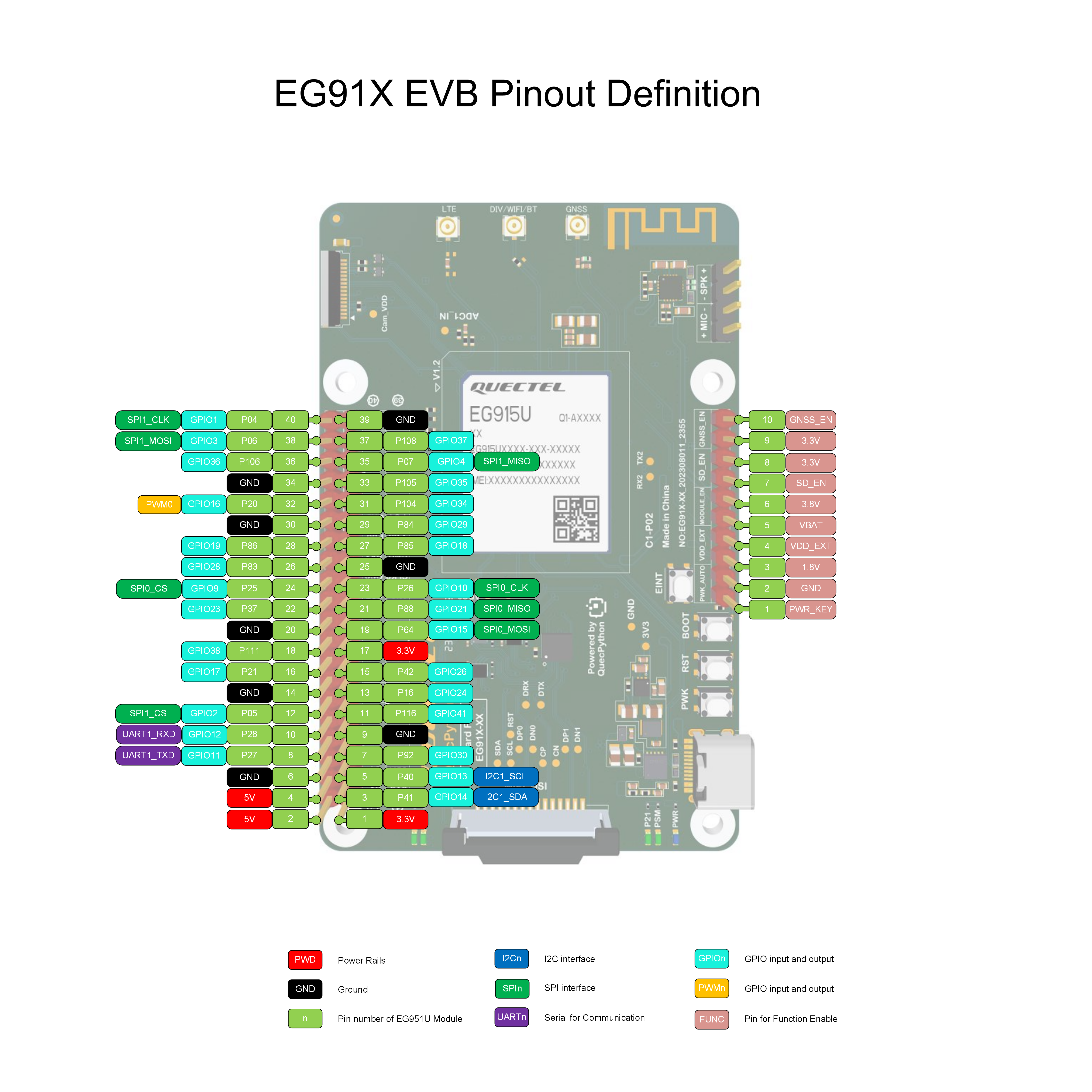
The main pin placement of the evaluation board is shown in the following figure:
Note
For more information about the evaluation board, please visit https://python.quectel.com/en/resource-download?cid=252.
Evaluation Board Configuration#
The detailed assignment of the peripheral interfaces on the evaluation board is as follows:
| No. | Name | Model | Silkscreen | Comment |
|---|---|---|---|---|
| 1 | USB Type-C Interface | - | - | - |
| 2 | SIM Card Slot 1 | SMN-315-ARP7 | SIM1 | Nano-SIM |
| 3 | SIM Card Slot 2 | MUP-C7809-1 | SIM2 | E-SIM |
| 4 | SD Card Slot | TF-101A-P3 | SD 2.0 | Before using the SD card, enable SD to provide power to the SD card in the 10-Pin Header. |
| 5 | USB Power Supply Switch | - | USB_ON/OFF | When the switch is normally closed, Type-C supplies power to the module and evaluation board, and USB can be connected normally. When the USB switch is normally open, Type-C supplies power only to the evaluation board. In this case, the module is not powered. |
| 6 | MIPI Interface | - | MIPI_DSI | When the main module is EG91X series, it supports MIPI LCD and is fully compatible with Raspberry Pi peripherals. |
| 7 | Camera Interface | - | - | The evaluation board supports customized SPI cameras with a maximum of 300,000 pixels. |
| 8 | MIC&SPK Interface | AW8733A- | +MIC-/-SPK+ | - |
| 9 | 40-Pin Header | - | - | Onboard 40-Pin header; For details, see the above figure and table. |
| 10 | 10-Pin Header | - | - | Onboard 10-Pin header; For details, see the above figure and table. |
| 11 | ADC Interface | - | ADC1_IN | ADC testing interface |
| 12 | PWK Botton | - | PWK | Turn-on button |
| 13 | RST Button | - | RST | Reset button |
| 14 | BOOT Button | - | BOOT | Firmware burning button |
| 15 | Antenna Interfaces | - | LTE DIV/WIFI/BT GNSS |
LTE antenna connector DIV/Wi-Fi/Bluetooth antenna connector GNSS antenna connector |
The evaluation board has 5 functional indication LEDs, as follows:
- P21: Power indication LED.
- PSM: Module Pin 1, PSM indication LED.
- SCK1: SIM1 detection indication LED, lights up when SIM1 is inserted.
- SCK2: SIM2 detection indication LED, lights up when SIM2 is inserted.
- PWR: Power indication LED.
The positions of the above indication LEDs refer to the silkscreen on the top of the evaluation board mentioned in the previous text (the side where the module is located is the top).
Evaluation Board Interfaces#
Pin Assignment of 10-Pin Header
| Header | No. | Silkscreen | Function |
|---|---|---|---|
| 10-Pin | 1 | PWK_AUTO | POWERKEY |
| 10-Pin | 2 | PWK_AUTO | GND |
| 10-Pin | 3 | VDD_EXT | 1.8 V |
| 10-Pin | 4 | VDD_EXT | VDD_EXT |
| 10-Pin | 5 | MODULE_EN | 3.8 V |
| 10-Pin | 6 | MODULE_EN | 3.8 V |
| 10-Pin | 7 | SD_EN | SD_EN |
| 10-Pin | 8 | SD_EN | 3.3 V |
| 10-Pin | 9 | GNSS_EN | 3.3 V |
| 10-Pin | 10 | GNSS_EN | GNSS_EN |
- 1 & 2: Auto turn on
- 3 & 4: Provide power externally when connected and test power consumption when disconnected
- 5 & 6: Connect DCDC to power the module
- 7 & 8: Enable SD power supply
- 9 & 10: Enable GNSS active power supply
When testing power consumption, make sure to switch off the USB power supply switch (USB_ON/OFF) on the back of the evaluation board.
Singular-pin Assignment of 40-Pin Header
| No | Name | Function Multiplexing | Function | NO | Name | Function Multiplexing | Function |
|---|---|---|---|---|---|---|---|
| 1 | 3V3 | - | 3.3 V Output | 2 | 5V | - | 5 V Output |
| 3 | SDA | I2C1_SDA GPIO14 |
I2C1 Data General Purpose Input/Output |
4 | 5V | - | 5 V Output |
| 5 | SCL | I2C1_SCL GPIO13 |
I2C1 Clock General Purpose Input/Output |
6 | GND | - | Ground |
| 7 | P92 | GPIO30 | General Purpose Input/Output | 8 | TXD | UART1_TXD | UART1 Send |
| 9 | GND | - | Ground | 10 | RXD | UART1_RXD | UART1 Recv |
| 11 | P116 | GPIO41 | General Purpose Input/Output | 12 | P05 | GPIO2 SPI1_CS |
General Purpose Input/Output SPI1 Chip Select |
| 13 | P16 | GPIO24 | General Purpose Input/Output | 14 | GND | - | Ground |
| 15 | P42 | GPIO26 | General Purpose Input/Output | 16 | P21 | GPIO17 | General Purpose Input/Output |
| 17 | 3V3 | - | 3.3 V Output | 18 | P111 | GPIO38 | General Purpose Input/Output |
| 19 | MO0 | SPI0_MOSI GPIO15 |
SPI0 Master Output Slave Input General Purpose Input/Output |
20 | GND | - | Ground |
| 21 | MI0 | SPI0_MISO GPIO21 |
SPI0 Master Input Slave Output General Purpose Input/Output |
22 | P37 | GPIO23 | General Purpose Input/Output |
| 23 | CLK0 | SPI0_CLK GPIO10 |
SPI0 Clock General Purpose Input/Output |
24 | CS0 | SPI0_CS GPIO9 |
SPI0 Chip Select General Purpose Input/Output |
| 25 | GND | - | Ground | 26 | P83 | GPIO28 | General Purpose Input/Output |
| 27 | P85 | GPIO18 | General Purpose Input/Output | 28 | P86 | GPIO19 | General Purpose Input/Output |
| 29 | P84 | GPIO29 | General Purpose Input/Output | 30 | GND | - | Ground |
| 31 | P104 | GPIO34 | General Purpose Input/Output | 32 | P20 | GPIO16 PWM0 |
General Purpose Input/Output PWM0 Output |
| 33 | P105 | GPIO35 | General Purpose Input/Output | 34 | GND | - | Ground |
| 35 | P07 | GPIO04 SPI1_MISO |
General Purpose Input/Output SPI1 Master Input Slave Output |
36 | P106 | GPIO36 | General Purpose Input/Output |
| 37 | P108 | GPIO37 | General Purpose Input/Output | 38 | P06 | GPIO3 SPI1_MOSI |
General Purpose Input/Output SPI1 Master Output Slave Input |
| 39 | GND | - | Ground | 40 | P04 | GPIO1 SPI1_CLK |
General Purpose Input/Output SPI1 Clock |
Getting Started Preparation#
First, you need a computer running Windows 10 or above.
- Step 1: Connect the Evaluation Board
Connect the evaluation board to the computer's USB port using a USB Type-C cable for power supply.
- Step 2: Turn On the Development Board
Long press the PWRKEY button to turn on the board. Before pressing the PWRKEY button, make sure the power supply voltage is stable. It is recommended to have a time interval of not less than 30 ms between powering up and pressing the PWRKEY button. If you want the board to power up and turn on automatically without the need for a turn-off function, you can directly short the two pins with PWK_AUTO silkscreen on the 10-Pin header.
After performing the above operations, wait for the power indication LED on the board to light up (the silkscreen on the board indicates the PWR LED, refer to the previous section on indication LEDs).
If the PWR LED lights up, the board has been successfully turned on