
EC2X EVB Introduction
Supported Modules
Supported module models
Feature List
Basic Overview
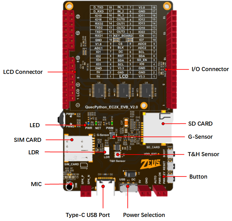
The QuecPython_EC2X_EVB is specifically designed for QuecPython. It is a small and portable "pocket-sized" EVB with rich features, such as temperature and humidity sensor, acceleration sensor, SIM card slot, SD card slot, LCD connector, LDR and MIC.
The EVB is equipped with a Type-C interface, so developers only need a USB Type-C cable to easily manipulate the EVB.
The EVB is equipped with the EC200U series module. For details, see EC200U-EU.
Feature Description
The main components and interface layout of the EVB are shown in the figure below.
Document download
EVB Resources
EVB Interface
J5 Pin Assignment
| Pin Header | Pin No. | Name | Feature |
|---|---|---|---|
| J5 | - | VCC_5V | 5V |
| J5 | - | VCC_5V | 5V |
| J5 | - | GND | Ground |
| J5 | 24 | IO3 | GPIO3 |
| J5 | 25 | IO4 | GPIO4 |
| J5 | 26 | IO2 | GPIO2 |
| J5 | 27 | IO1 | GPIO1 |
| J5 | 44 | ADC1_IN | ADC1 |
| J5 | - | VDD_EXT | 1.8 V |
J6 Pin Assignment
| Pin Header | Pin No. | Name | Feature |
|---|---|---|---|
| J6 | - | V3.3 | 3.3 V |
| J6 | - | GND | Ground |
| J6 | - | GND | Ground |
| J6 | 3 | IO9 | GPIO9 |
| J6 | 119 | SD_EN | SD card enable control |
| J6 | 142 | SDA | I2C1 |
| J6 | 141 | SCL | I2C1 |
| J6 | 43 | ADC2_IN | ADC2 |
| J6 | 45 | ADC0_IN | ADC0 |
J7 Pin Assignment
| Pin Header | Pin No. | Name | Feature |
|---|---|---|---|
| J7 | - | GND | Ground |
| J7 | 138 | RX1 | UART1 |
| J7 | 137 | TX1 | UART1 |
| J7 | 67 | TX2 | UART2 |
| J7 | 68 | RX2 | UART2 |
| J7 | 65 | IO18 | GPIO18 |
| J7 | 64 | IO19 | GPIO19 |
| J7 | 11 | D_RX | UART |
| J7 | 12 | D_TX | UART |
J10 Pin Assignment
| Pin Header | Pin No. | Name | Feature |
|---|---|---|---|
| J10 | 136 | IO7 | GPIO7 |
| J10 | 135 | IO6 | GPIO6 |
| J10 | 127 | IO22 | GPIO22 |
| J10 | 40 | IO10 | GPIO10 |
| J10 | 39 | IO13 | GPIO13 |
| J10 | 38 | IO12 | GPIO12 |
| J10 | 37 | IO11 | GPIO11 |
| J10 | - | GND | Ground |
| J10 | - | V3.8 | 3.8 V |
The following figure shows the pin assignment.

Tips
For more information about the EVB, please visit https://python.quectel.com/en/resource-download?cid=252
EVB Configuration
The EVB is equipped with various sensors and other peripherals. The pins of peripherals are shown in the table below.
| Pin No. | Name | Model | Supported | Interface Type |
|---|---|---|---|---|
| 41 and 42 | Temperature and Humidity Sensor | AHT20 | Yes | I2C |
| 45 | LDR | GT36528 | Yes | ADC |
| 41 and 42 | G-Sensor | QMA7981 | Yes | I2C |
| 75 and 77 | Microphone | GMI6050P-66DB | Yes | SPK |
| 73 and 74 | Power Amplifier Chip | NS4160 | Yes | SPK |
| 122–125 | LCD (Choose the package with screen) | ST7789 | Yes | SPI |
| 28–34 | SD_CARD | XKTF-NO2-N | Yes | SPI |
Getting Started Preparation
First, you will need a computer running Windows 10 or later.
- Step 1: Antenna Installation
Install the antenna that comes with the development board. Place it in the LTE antenna slot and insert the SIM card into the SIM card slot on the development board. If you need to use GNSS or BTWIFI functionality, install antennas in their respective slots.
- Step 2: Connecting the Development Board
Use a USB Type-C data cable to connect the Type-C port on the development board to a USB port on your computer to provide power.
- Step 3: Development Board Power Settings
Set the power selection switch on the development board to USB, and short-circuit the PWK_ON jumper on the development board to AUTO (power on automatically when powered).
- Step 4: Powering On the Development Board
Press and hold PWK until the power indicator light on the mainboard (labeled as POW) lights up. If you short-circuited PWK_ON in the previous step, there's no need to press PWK; the board will power on automatically.
Once you've completed these steps, a constant POW light indicates a successful power-on.